Controlling a voltage source converter in a DC system

a voltage source converter and dc system technology, applied in the field of voltage source converters, can solve the problems of oscillations being damped and the risk of oscillation between the two poles, and achieve the effects of avoiding the introduction of potentially expensive components, efficient oscillation damping of power swings, and increasing the footprint of the converter

Active Publication Date: 2021-02-23
HITACHI ENERGY SWITZERLAND AG
View PDF11 Cites 0 Cited by
  • Summary
  • Abstract
  • Description
  • Claims
  • Application Information

AI Technical Summary

Benefits of technology

[0016]controlling the converter valves to generate at least one AC waveform and to reduce oscillations between the converters.
[0018]control the converter valves to generate at least one AC waveforms and to reduce oscillations between the converters.
[0020]The present invention has a number of advantages. It enables efficient oscillations damping of power swings between the two converters. Moreover, as the damping is performed using control it is possible to avoid introducing potentially expensive components having losses, such as resistors. Resistors are also bulky and thus increase the footprint of the converter. The degree of damping may also be flexibly set. The control is also easily introduced in a converter through merely adding some software.

Problems solved by technology

However, when controlling both the converters in this control mode when they are interconnected on the AC side, there is a risk of oscillations between the two poles.
However, the oscillations being damped in this document are oscillations caused by an electrical LCL filter connected between the AC side of a converter and an AC system.

Method used


Image

  • Controlling a voltage source converter in a DC system
  • Controlling a voltage source converter in a DC system
  • Controlling a voltage source converter in a DC system

Examples


Embodiment Construction

[0029]In the following, a detailed description of preferred embodiments of the invention will be given.

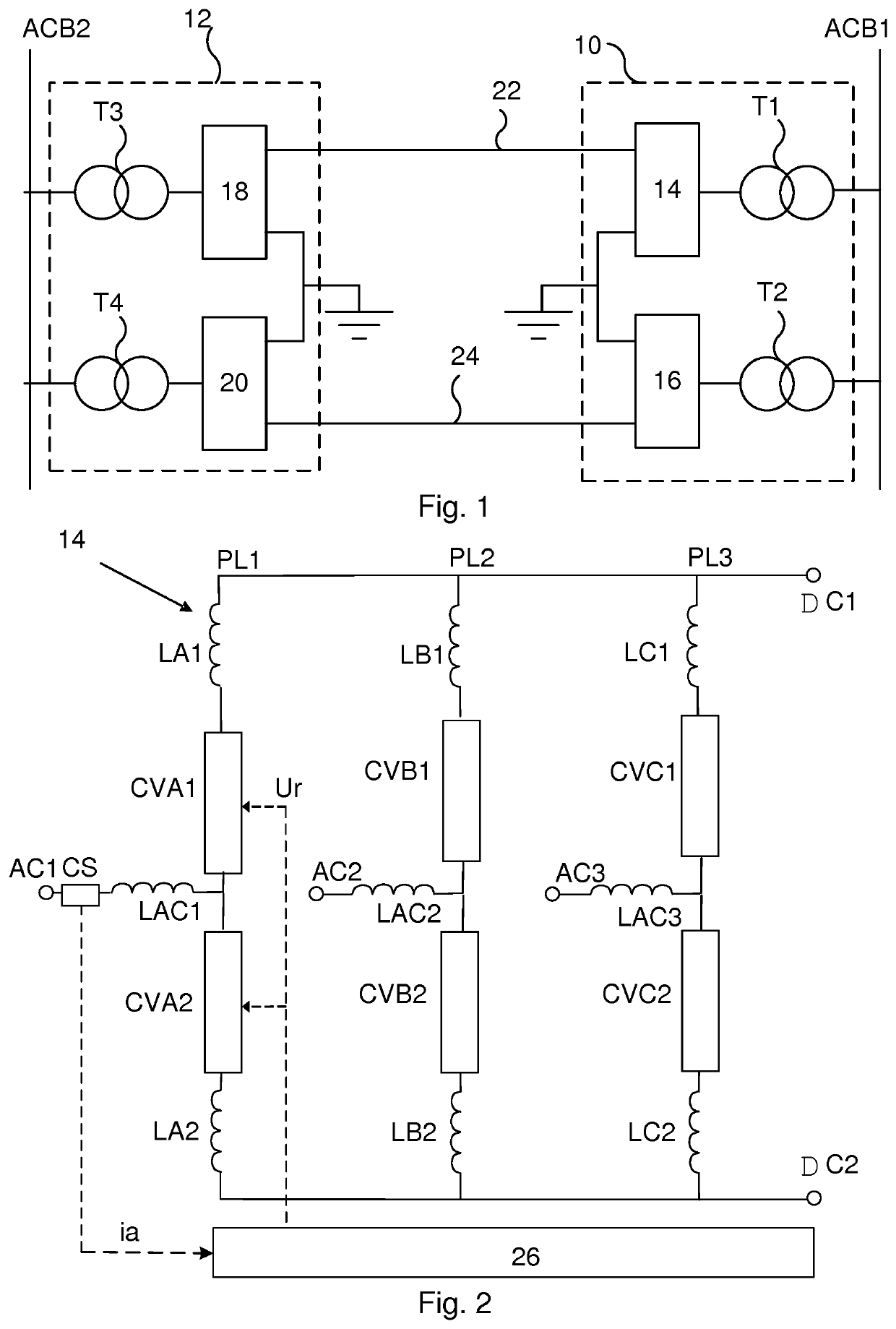
[0030]FIG. 1 shows a single line diagram of two converter stations 10 and 12, each connected to a separate Alternating Current (AC) system and being interconnected by a Direct Current (DC) system, which may be a High Voltage Direct Current (HVDC) power transmission system. The DC system is a bipole system and therefore there is a first pole 22 and a second pole 24. For this reason also the first converter station 10 comprises a first and second converter 14 and 16 and the second converter station 12 comprises a third and a fourth converter 18 and 20. The converters convert between AC and DC and therefore each converter has a DC side facing the DC system and an AC side facing an AC system.

[0031]In the present example the first converter 14 of the first converter station 10 is connected to a first AC bus ACB1 via a first transformer T1 and the second converter 16 is also connected to...


PUM


Abstract

A first voltage source converter and converter station including such a first voltage source converter, as well as a method and computer program product for controlling the first voltage source converter are disclosed. The first voltage source converter has a DC side for connection to a DC system, has an AC side for connection to an AC system and is interconnected with an AC side of a second voltage source converter, which has a DC side connected to the DC system. The first voltage source converter includes a number of converter valve pairs, each being connected to a corresponding AC phase of the AC system and a control unit controlling the converter valves to generate at least one AC waveform and to reduce oscillations between the converters.

Description

FIELD OF INVENTION[0001]The present invention relates to a first voltage source converter and a converter station comprising the first voltage source converter as well as to a method and computer program product for controlling the first voltage source converter.BACKGROUND[0002]Voltage source converters are often used for converting between alternating current (AC) and Direct Current (DC), such as between three-phase AC and DC. A converter is then typically provided in a converter station and has a DC side connected to a DC system and an AC side connected to an AC system. The converter is then made up of a number of phase legs, one for each phase, where each phase leg comprises two phase arms, an upper and a lower phase arm. Each phase arm then comprises a corresponding converter valve, where the valves of a phase leg are together used for forming an AC waveshape.[0003]The DC system may be a bipole DC system, i.e. a system comprising two DC poles; a positive pole and a negative pole...

Claims


Application Information

Patent Timeline
Patent Type & Authority Patents(United States)
IPC IPC(8): H02J3/36H02M7/757
CPCH02J3/36H02M7/7575H02J2003/365H02M7/757Y02E60/60
Inventor JIANG-HÄFNER, YINGABDALRAHMAN, ADILHOLMBERG, PER
Owner HITACHI ENERGY SWITZERLAND AG
Why Eureka
Try Eureka