Systems and methods of autonomous solar exposure

a solar panel and solar panel technology, applied in the direction of battery/fuel cell control arrangement, light to electrical conversion, lighting and heating apparatus, etc., can solve the problems of slow speed, affecting the operation of conventional solar panels, and limiting the exposure of solar panels to the sun, so as to achieve the effect of maximizing the exposure of the solar panel of the vehicl

Active Publication Date: 2021-02-09
TOYOTA MOTOR ENGINEERING & MANUFACTURING NORTH AMERICA
View PDF18 Cites 3 Cited by
  • Summary
  • Abstract
  • Description
  • Claims
  • Application Information

AI Technical Summary

Benefits of technology

[0008]The method may further comprise selecting the one or more locations based on locations at which the vehicle can be automatically parked. This is to optimize the solar exposure needed to meet the energy requirements for recharging the vehicle's power storage device to the desired SOC. This also minimizes the energy required to travel to the one or more locations, and return from the one or more locations to the first location.
[0013]The method may further comprise repositioning the vehicle to maximize exposure of the vehicle's solar panel to a solar energy source.

Problems solved by technology

However, even though the roof of a vehicle often experiences the greatest sun exposure, the solar power that can be captured is only capable of charging a small portion of a vehicle's power storage device (e.g., battery).
In some vehicles, the power storage device can be fully recharged through solar power, but it is done at a slow rate.
The operation of conventional solar roofs is further hampered by conditions that impede exposure of the solar roof to the sun, e.g., when the vehicle is parked inside a garage, when the vehicle is being operated in cloudy or less-than-ideal weather, etc.

Method used


Image

  • Systems and methods of autonomous solar exposure
  • Systems and methods of autonomous solar exposure
  • Systems and methods of autonomous solar exposure

Examples


Embodiment Construction

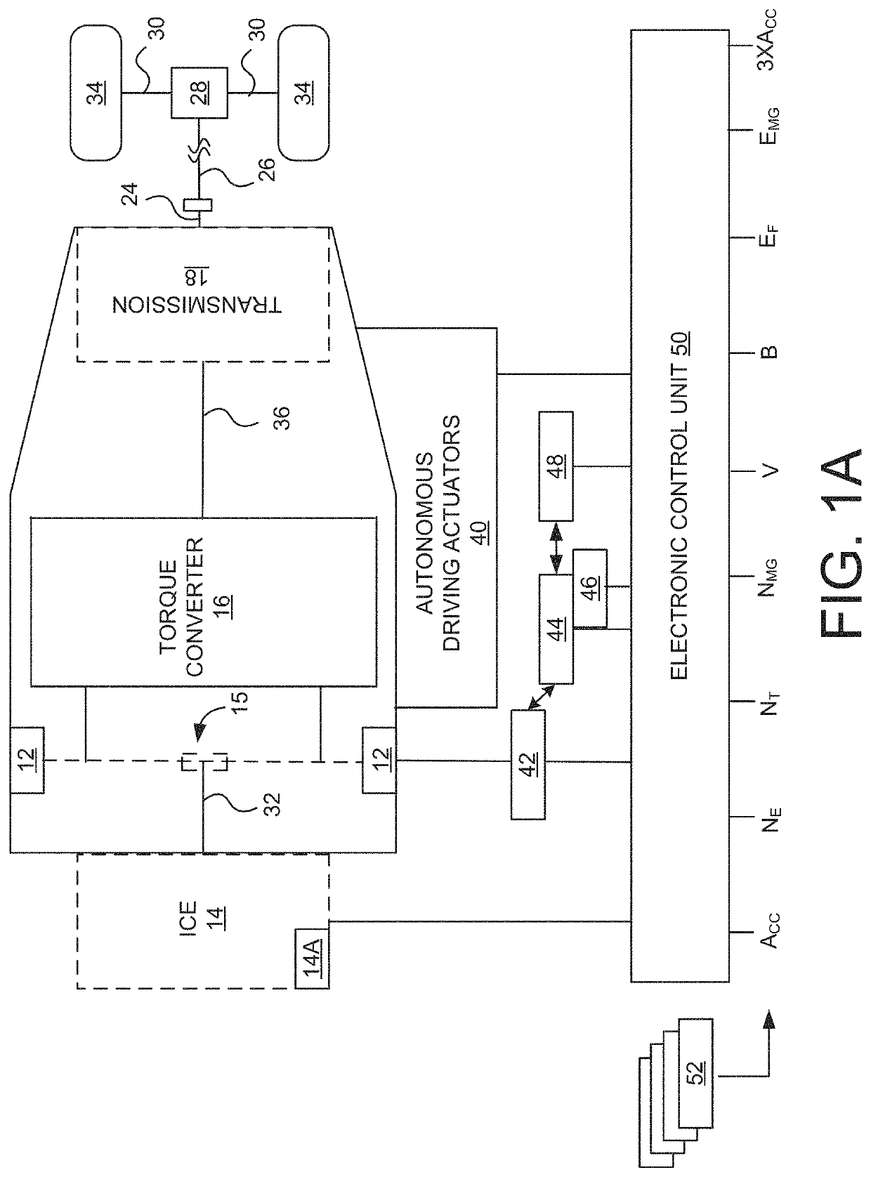
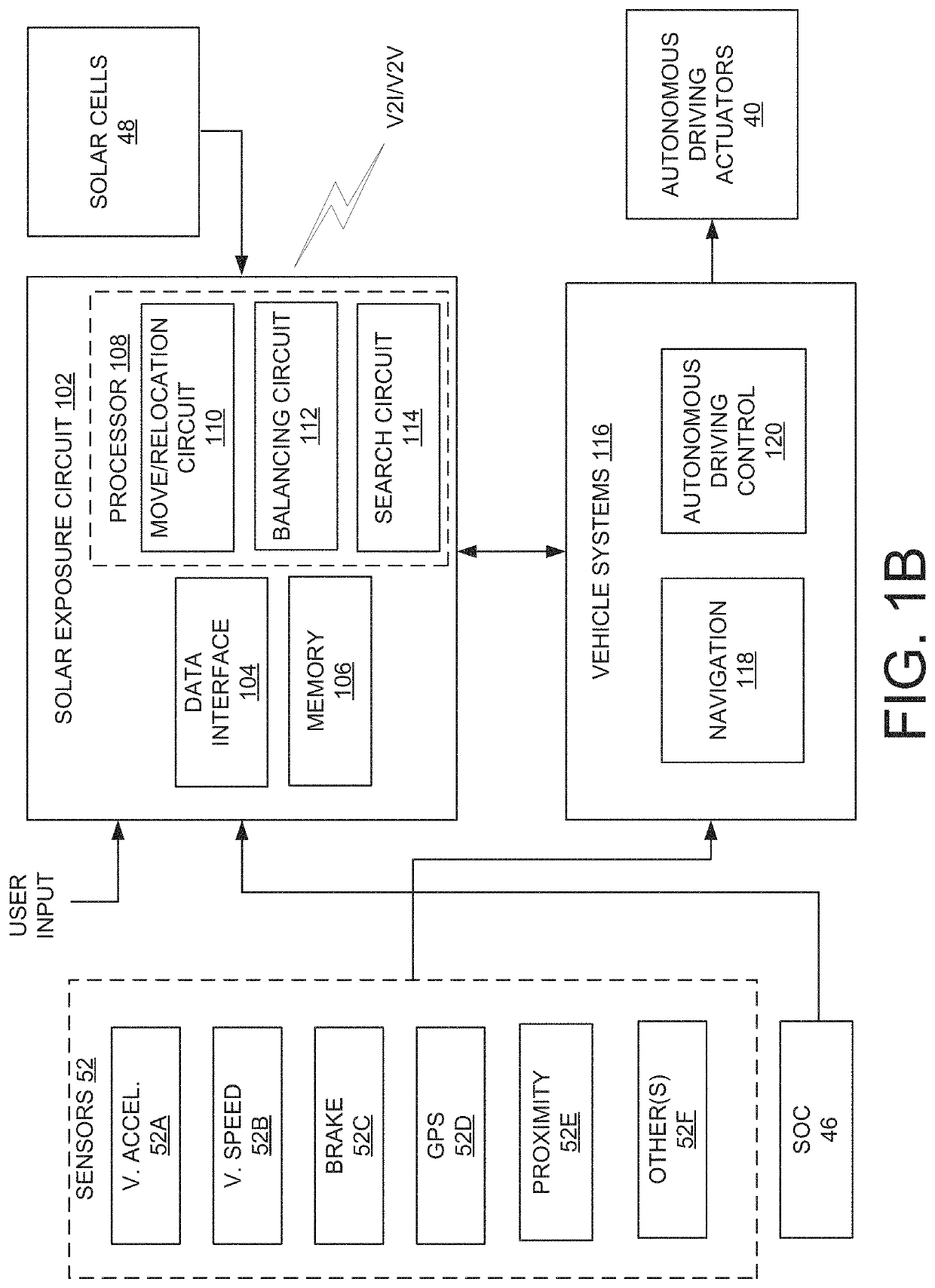
[0004]In accordance with one embodiment, a computer-implemented method, comprises determining whether a vehicle is in a parked state. Upon a determination that the vehicle is in the parked state, a first location of the vehicle may be determined. The vehicle's power storage device state of charge may be measured. Solar exposure that can be used by a solar panel of the vehicle to recharge the vehicle's power storage device to a desired state of charge relative to the measured power storage device state of charge is determined within a range of operation relative to the first location. An autonomous driving mode of the vehicle is enabled. The vehicle is autonomously operated to travel to one or more locations at which the solar exposure meets energy requirements for recharging the vehicle's power storage device to the desired SOC. The vehicle is automatically parked for a determined time period to recharge the vehicle's power storage device to the desired SOC. The vehicle may then be ...


PUM


Abstract

Systems and methods of autonomously driving a vehicle to one or more locations, or repositioning the vehicle, to achieve optimal solar exposure are provided. Operating conditions of the vehicle, environmental conditions, as well as road conditions may be considered when determining whether or not to move, relocate, or reposition the vehicle to achieve optimal solar exposure. The optimal solar exposure is that which allows a power storage device of the vehicle to be charged to a desired state of charge. Additional considerations, such as the time needed to travel to a new location(s) and return from the location(s) in time for a next use of the vehicle, may be taken into account. Any energy expenditures that may result from traveling to / from the new location(s) may also be considered.

Description

TECHNICAL FIELD[0001]The disclosed technology relates generally to automotive systems, and more particularly, some embodiments relate to autonomous operation of a vehicle to achieve optimal solar exposure.DESCRIPTION OF THE RELATED ART[0002]Some vehicle manufacturers have begun utilizing alternative power sources to improve fuel economy, as well as improve the overall operating efficiency and environmental performance of their vehicles. One such type of alternative power source is solar power. Solar power is a renewable energy source, and can be harnessed through the use of solar cells that convert light energy of the sun into electrical energy (photovoltaic power generation).[0003]Solar cells can be incorporated into a vehicle's roof as the roof of a vehicle is an area that generally experiences the most exposure to the sun (versus, for example, the side panels / doors of the vehicle). However, even though the roof of a vehicle often experiences the greatest sun exposure, the solar p...

Claims


Application Information

Patent Timeline
Patent Type & Authority Patents(United States)
IPC IPC(8): B60L8/00F24S50/20B60L58/13B60K16/00
CPCB60L8/003B60L58/13F24S50/20B60K2016/003H02S10/40Y02E10/47Y02E10/50Y02T10/70Y02T10/7072
Inventor GAITHER, GEOFFREY D.
Owner TOYOTA MOTOR ENGINEERING & MANUFACTURING NORTH AMERICA
Why Eureka
Try Eureka