
Apparatus and method for decoding polar codes

a technology of polar codes and apparatuses, applied in the direction of electrical apparatus, code conversion, coding, etc., can solve the problems of high latency, high latency of scan decoding, etc., and achieve low storage and computational complexity. , the effect of low complexity

Active Publication Date: 2021-01-12
KOREA UNIV RES & BUSINESS FOUND
View PDF9 Cites 0 Cited by
  • Summary
  • Abstract
  • Description
  • Claims
  • Application Information

AI Technical Summary

Benefits of technology

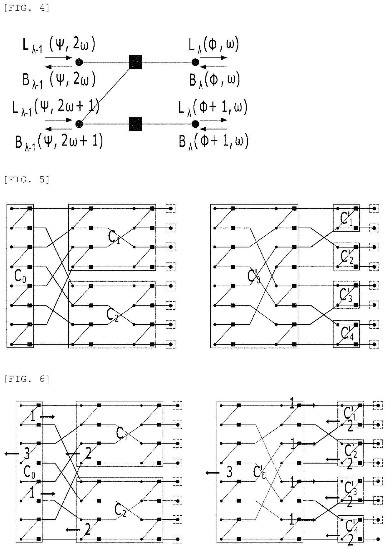
[0011]A technical object to be achieved by the present disclosure is to provide a method and an apparatus for decoding polar codes which are capable of adjusting a latency, a storage complexity, and a computational complexity by changing a decoding schedule in accordance with requirements of the system.
[0025]According to the present disclosure, it is possible to satisfy the requirements of various systems by adjusting a level of parallelism to be flexibly changed from the most sequential level to the most parallel level, and thus to adjust the latency, the storage complexity, and the computational complexity.
[0026]That is, according to the present disclosure, when a level of parallelism of the decoding scheme is adjusted, the latency and the complexity may be adjusted by a trade-off relationship. Therefore, the decoding schedule may be flexibly changed depending on whether a latency of the decoding is important or the complexity is important, and thus it is possible to cope with various system requirements without other decoding schemes.

Problems solved by technology

Therefore, the SC based decoding schemes have good performance, but are disadvantageous in that storage and computational complexities are low and the latency is high and thus studies are actively conducted to solve the disadvantages.
Therefore, similarly to the SC decoding, the SCAN decoding has high latency but has low storage and computational complexities.
As described above, the SCAN has low storage and computational complexities and high latency, but the BP has low latency and high storage and computational complexities.
Therefore, the SCAN and the BP cannot be selected in a system where a reasonable latency and complexity are required as an intermediate point or requirements vary depending on the working environment.

Method used


Image

  • Apparatus and method for decoding polar codes
  • Apparatus and method for decoding polar codes
  • Apparatus and method for decoding polar codes

Examples


Embodiment Construction

[0043]Hereinafter, exemplary embodiments of the present disclosure will be described more fully with reference to the accompanying drawings for those skilled in the art to easily implement the present disclosure. As those skilled in the art would realize, the described embodiments may be modified in various different ways, all without departing from the spirit or scope of the present disclosure.

[0044]In order to clearly illustrate the present disclosure, parts not related to the description are omitted. Accordingly, the drawings and description are to be regarded as illustrative in nature and not restrictive. Like reference numerals designate like elements throughout the specification. Therefore, reference numerals which are used in previous drawings may be used for another drawing.

[0045]The size and thickness of the components shown the drawings are optionally determined for better understanding and ease of description, and the present disclosure is not limited to the examples show...


PUM


Abstract

The present disclosure relates to a method and an apparatus for decoding polar codes and the polar code decoding method according to an exemplary embodiment of the present disclosure is a polar code decoding method performed by a polar code decoding apparatus which includes receiving a code word vector generated by polar encoding; and decoding the code word vector based on a soft cancellation (SCAN) decoding method and a round-trip belief propagation (BP) decoding method, in the decoding, an inner code of the code word vector may be decoded by the round-trip belief propagation method and an outer code may be decoded by the SCAN decoding method.

Description

CROSS-REFERENCE TO RELATED APPLICATIONS[0001]This application claims the priority of Korean Patent Application No. 10-2018-0123795 filed on Oct. 17, 2018, in the Korean Intellectual Property Office, the disclosure of which is incorporated herein by reference.BACKGROUNDField[0002]The present disclosure relates to a method and an apparatus for decoding polar codes, and more particularly, to soft-out decoding method and apparatus which change a decoding schedule in accordance with requirements of a system to adjust a latency, a storage complexity, and a computational complexity.Description of the Related Art[0003]A polar code is a linear block code proposed by Arikan and is a first error correction code proved to have an explicit construction in a binary-input discrete memoryless channel and theoretically achieve Shannon's channel capacity. Due to this property, recently, the polar code is being actively studied in the error correction code field. Recently, the polar code is adopted as...

Claims


Application Information

Patent Timeline
Patent Type & Authority Patents(United States)
IPC IPC(8): H03M13/11H03M13/29H03M13/13H03M13/45
CPCH03M13/2927H03M13/13H03M13/458H03M13/1111H03M13/1191H03M13/45H03M13/3707H03M13/611H03M13/6502
Inventor HEO, JUNLEE, SUNG HOON
Owner KOREA UNIV RES & BUSINESS FOUND
Learn More