
Shark barrier

a barrier and shark technology, applied in shark screens, mechanical equipment, transportation and packaging, etc., can solve the problems of not forming a complete barrier, other aquatic creatures such as turtles and dolphins are often caught and killed in the nets, and it is not practical to protect large areas

Active Publication Date: 2021-01-05
STELLENBOSCH UNIVERSITY
View PDF9 Cites 1 Cited by
  • Summary
  • Abstract
  • Description
  • Claims
  • Application Information

AI Technical Summary

Benefits of technology

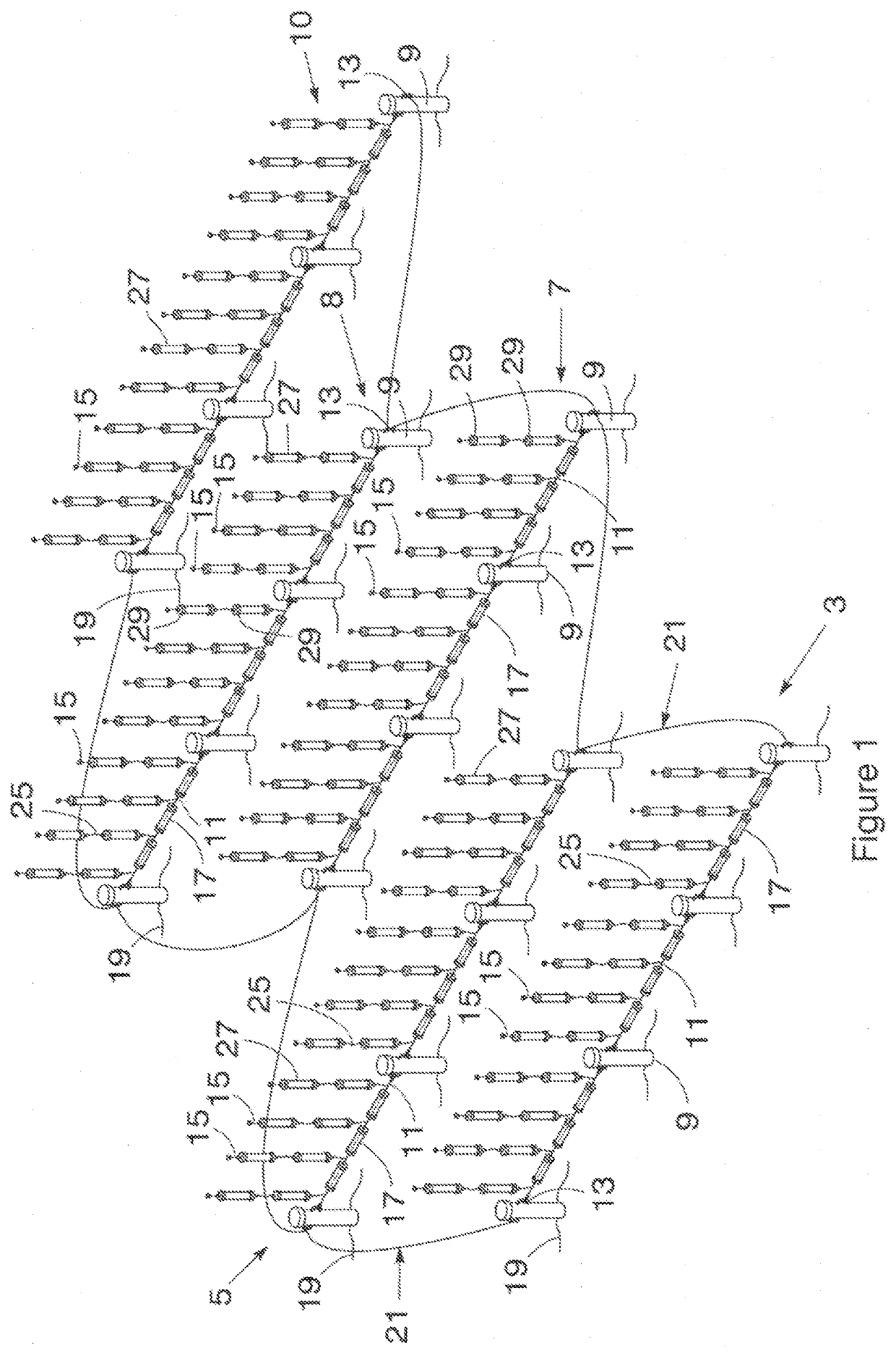
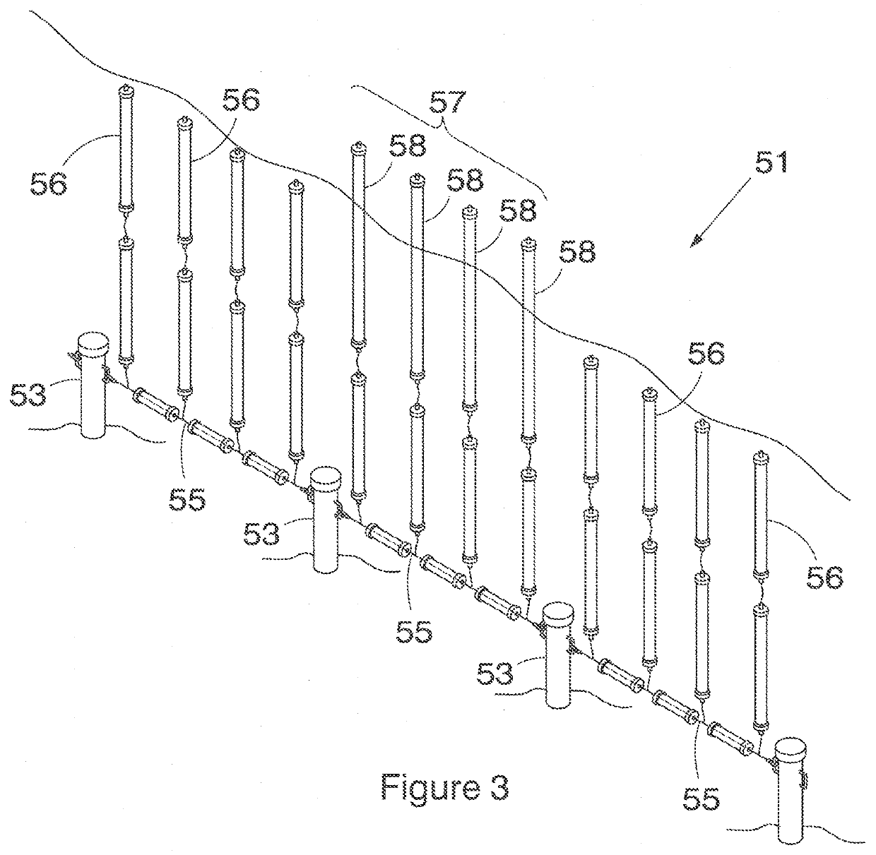
This invention is a shark barrier that uses a flexible anchoring system and multiple buoyant resiliently flexible elongate members to prevent sharks from entering a certain area. The buoyant members are connected along a continuous flexible spine and can move upwardly to repel sharks. The shark barrier can have multiple rows of interconnected anchors, and the anchor's heads can be attached to a connecting element. The flexible spine can be a cable, rope, chain, or buoyant tube, and there can be a separate flexible connecting element between each pair of adjacent anchors. The invention can also have a passageway for water vehicles and a power source for providing electricity through the connecting element. Overall, the technical effects of this invention are to provide a shark barrier that is effective in preventing shonline and to provide a safe area for water activities.

Problems solved by technology

Although fairly effective in reducing the number of sharks, shark nets do not form a complete barrier and sharks can swim over, under or around the nets.
In addition to this, other aquatic creatures such as turtles and dolphins are often caught and killed in the nets.
Although exclusion nets are not designed to capture sharks and are therefore generally less detrimental to the environment, the nets exclude generally all marine animals larger than the net mesh, and are also not suitable for certain high-swell regions and are impractical for protecting large areas.
It has also been found that because the shark barrier is mostly submerged, wear and tear, such as rust or biofouling, can cause the connection points between segments to be points of weakness.

Method used


Image

  • Shark barrier
  • Shark barrier
  • Shark barrier

Examples


Embodiment Construction

[0032]In the embodiment of the invention shown in FIG. 1 the shark barrier (1) includes five generally parallel adjacent linear rows (3, 5, 7, 8, 10) of spaced apart anchors (9) interconnected by separate flexible connecting elements, in this embodiment connection cables (11). Each flexible connection cable is secured at one end to a securing formation (13) located at an operatively upper portion of an anchor and at its opposite end to a securing formation (13) of an adjacent anchor. A plurality of spaced apart buoyant resiliently flexible elongate members (15) are secured at one end along a length of each connection cable and extend generally upwardly from the connection cable. The buoyant members (15) are spaced apart by means of tubular members, acting as spacers (17) fitted over the connection cables (11) and in between adjacent buoyant members.

[0033]The adjacent linear rows (3, 5, 7, 8, 10) are anchored into the sea floor (19) to be off-set relative to each other to form a stag...


PUM


Abstract

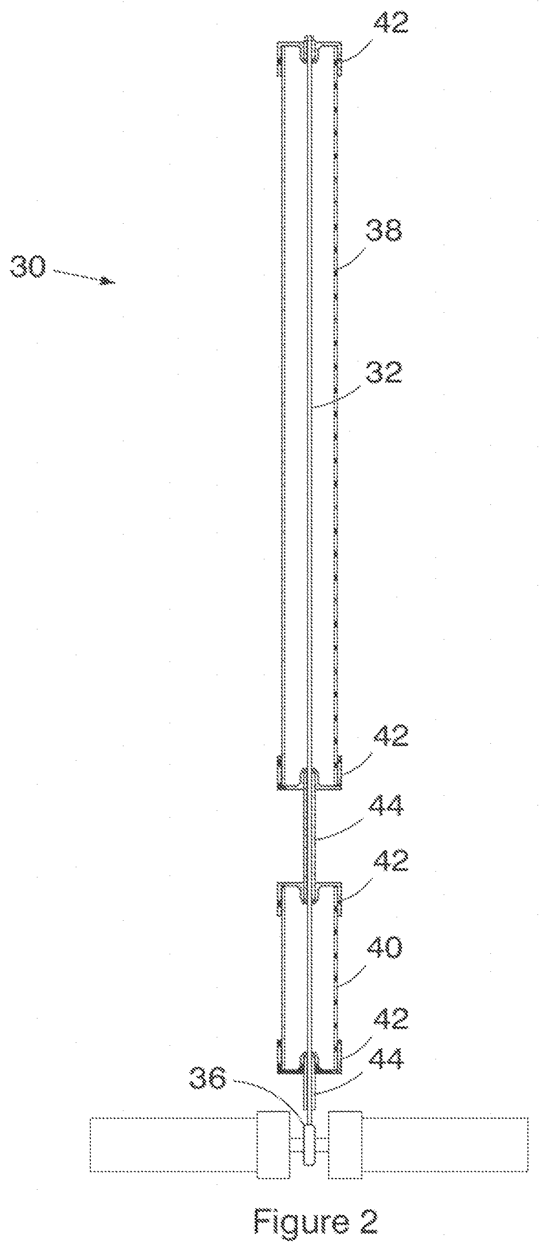
A shark barrier that comprises an anchoring assembly having a pair of anchors (9) with a flexible connecting element (11) extending between the anchors. The shark barriers also includes multiple spaced apart buoyant resiliently flexible elongate members (15) that are secured at one end along a length of the connecting element of the anchoring assembly to operatively extend generally upwardly from the connecting element. The buoyant members comprise an elongate flexible spine (32) that extends through a series of tubular members (38).

Description

CROSS-REFERENCE(S) TO RELATED APPLICATIONS[0001]This application claims priority from South African provisional patent application numbers 2016 / 02093, 2016 / 02094, 2016 / 02095, 2016 / 02096 and 2016 / 02097, which are incorporated by reference herein.FIELD OF THE INVENTION[0002]This invention relates to a barrier for preventing sharks from accessing designated areas.BACKGROUND TO THE INVENTION[0003]Sharks play a vital role in managing healthy ecosystems. The majority of shark species prey on fish and smaller aquatic life such as molluscs and clams. Bigger species of sharks, however, generally feed on larger animals such as sea lions, seals and bigger fish.[0004]Sharks have fallen victim to a reputation as fierce man-hunting predators and over the years various cases of shark attacks on humans have been documented.[0005]In order to combat shark attacks, coastlines and beaches are often safeguarded with anti-shark devices to reduce the encounters between people and sharks. Various anti-shar...

Claims


Application Information

Patent Timeline
Patent Type & Authority Patents(United States)
IPC IPC(8): E02B1/00B63C9/05A01M29/30B63C9/00F16B1/00
CPCE02B1/006A01M29/30B63C9/00B63C9/05F16B1/00B63C2009/0088F16B2001/0064F16B2200/93
Inventor RUTZEN, MICHAELANDREOTTI, SARABECKER, PIERREBARWELL, LAURIE
Owner STELLENBOSCH UNIVERSITY
Learn More