
Electrical protection device for mechanical equipment

a protection device and mechanical equipment technology, applied in the direction of emergency protection circuit arrangement, emergency protection arrangement for limiting excess voltage/current, electric apparatus, etc., can solve the problems of controller or terminal load damage, difficult to design the protection device, and error in response capability, so as to achieve effective isolation of damage

Active Publication Date: 2020-12-08
HIWIN TECH
View PDF26 Cites 0 Cited by
  • Summary
  • Abstract
  • Description
  • Claims
  • Application Information

AI Technical Summary

Benefits of technology

The present invention provides an electrical protection device for mechanical equipment. The device effectively isolates damage caused by transient surges while ignoring the response of electronic components in the system. The device is designed to simplify the design of the protection circuit and effectively block transient surge energy. The invention includes a pre-stage protection circuit and a post-stage protection circuit arranged in a way that the response of the post-stage protection circuit is delayed when a transient surge energy occurs.

Problems solved by technology

The transient surge enters the controller with the power supply path, causing damage to the controller or the terminal load.
In addition, electronic components of the same specifications can also cause errors in the response capability due to parameter errors.
Therefore, it is difficult to design the protection device.
Further, the available space inside each mechanical equipment is limited, so the space that the protection circuit can use is usually narrow.
Therefore, how to select suitable protection devices in this narrow space has become a problem that needs to be solved in the industry.

Method used


Image

  • Electrical protection device for mechanical equipment
  • Electrical protection device for mechanical equipment
  • Electrical protection device for mechanical equipment

Examples


Embodiment Construction

[0012]The electrical protection device, referenced by 10, of the present invention is a controller applied to a mechanical device, such as a robot, an electric gripper, a slide rail, etc.

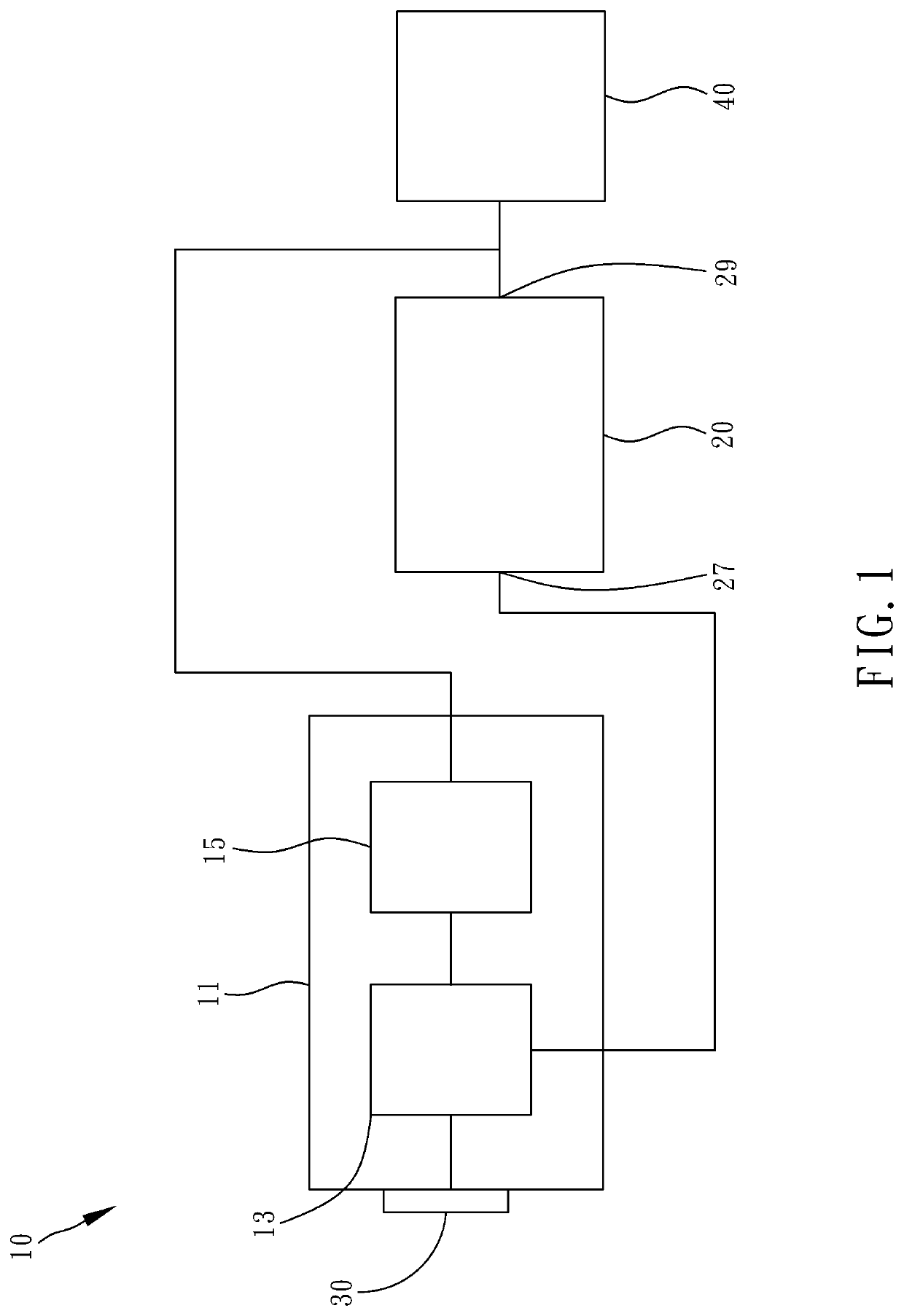
[0013]Referring to FIG. 1, the electrical protection device 10 connects a controller 20 and a power supply 30 to prevent the instantaneous surge energy generated by the power supply or the power lines from damaging the electronic components inside the controller 20 or the mechanical device. The load, referenced by 40, is an executing device of the mechanical device, such as an electric gripper, guideway, etc.

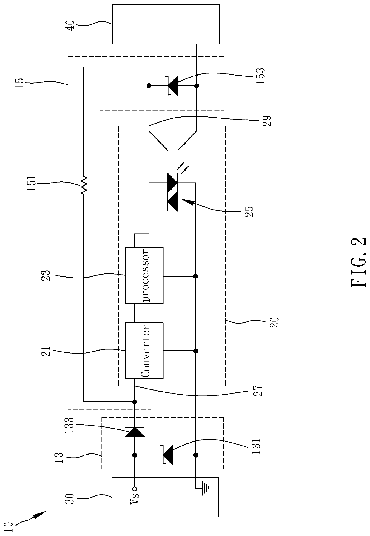
[0014]Referring to FIG. 2 and FIG. 1 again, the controller 20 comprises a converter 21, a processor 23 and a photo relay 25. The converter 21 connects the electrical protection device 10 and receives the power energy through the electrical protection device 10. The processor 23 connects the converter 21 and the photo relay 25 and is used to output a control command of the load 40, or to receive ...


PUM


Abstract

An electrical protection device used in a controller of a mechanical equipment is disclosed to include a circuit board, and a pre-stage protection circuit and a post-stage protection circuit formed on the circuit board. The pre-stage protection circuit connects a power supply and a pre-stage of the controller, providing an electrical protection condition such that when a transient surge energy of the power supply surpasses the electrical protection condition, the pre-stage protection circuit blocks the transient surge energy from entering the controller. The post-stage protection circuit connects pre-stage protection circuit and a post-stage of the controller. Further, when the transient surge energy occurs, a response speed of the post-stage protection circuit is slower than that of the pre-stage protection circuit. The electrical protection device of the invention effectively blocks transient surge energy, avoiding electronic system component damage of the mechanical equipment.

Description

BACKGROUND OF THE INVENTION1. Field of the Invention[0001]The present invention relates to electrical protection technology and more particularly, to an electrical device for mechanical equipment.2. Description of the Related Art[0002]A controller is a device used to control the operation of an automation or mechanical equipment, such as processing, measurement, and transportation. The operation process usually includes a variety of different itineraries, such as rotation, movement, and grabbing. A controller completes various strokes and operations through programs or instructional arrangements.[0003]During the operation of a controller, the power energy may be suddenly affected by the surrounding equipment, environmental equipment, power line sensing, lightning, and power contacts to produce a transient surge. The transient surge enters the controller with the power supply path, causing damage to the controller or the terminal load.[0004]At present, in order to prevent transient s...

Claims


Application Information

Patent Timeline
Patent Type & Authority Patents(United States)
IPC IPC(8): H02H9/04
CPCH02H9/04H02H9/041H02H9/00H02H9/005H02H3/00H02H9/042H02H9/044
Inventor CHANG, SHUN-KAIHUANG, YEN-SHUN
Owner HIWIN TECH
Learn More