
Container faucet assembly

a container and faucet technology, applied in the direction of liquid dispensing, liquid flow controllers, packaging, etc., can solve the problems of unsatisfactory assembling stability, liquid leakage, and difficulty in applying a force in the reverse direction to remove the knob b>2/b>′ from the container b>3/b>′, so as to improve the convenience of assembling and stable structure

Active Publication Date: 2020-11-03
LIN YEN LIN
View PDF6 Cites 2 Cited by
  • Summary
  • Abstract
  • Description
  • Claims
  • Application Information

AI Technical Summary

Benefits of technology

The present invention is a faucet assembly designed to improve assembly ease and create a stable structure. It includes a tubular member with flanges and a rear end extending through an engaging hole of a container, providing a positioning effect. A fastening member is threaded around the insertion section and abuts against the peripheral edge of the engaging hole for secure attachment. This faucet assembly offers convenient and secure assembly with a stable structure.

Problems solved by technology

However, when cleaning the faucet 3′ is desired, it is difficult to apply a force in the reverse direction for detaching the knob 2′ from the faucet 3′.
Furthermore, when the coupling hole 311′ is not aligned with a center of the front end of the tube 21′ during assembly, the first and second conical faces 211′ and 312′ cannot reliably abut against each other and could deform, leading to unsatisfactory assembling stability and leakage of the liquid.

Method used


Image

  • Container faucet assembly
  • Container faucet assembly
  • Container faucet assembly

Examples


Embodiment Construction

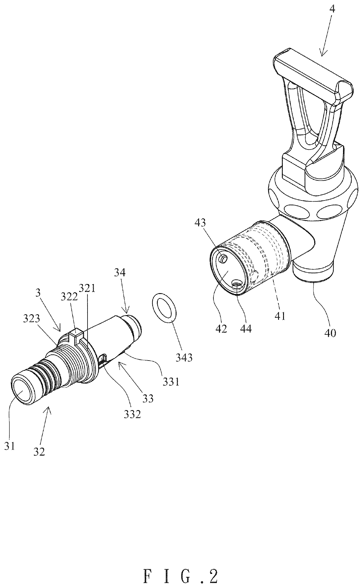
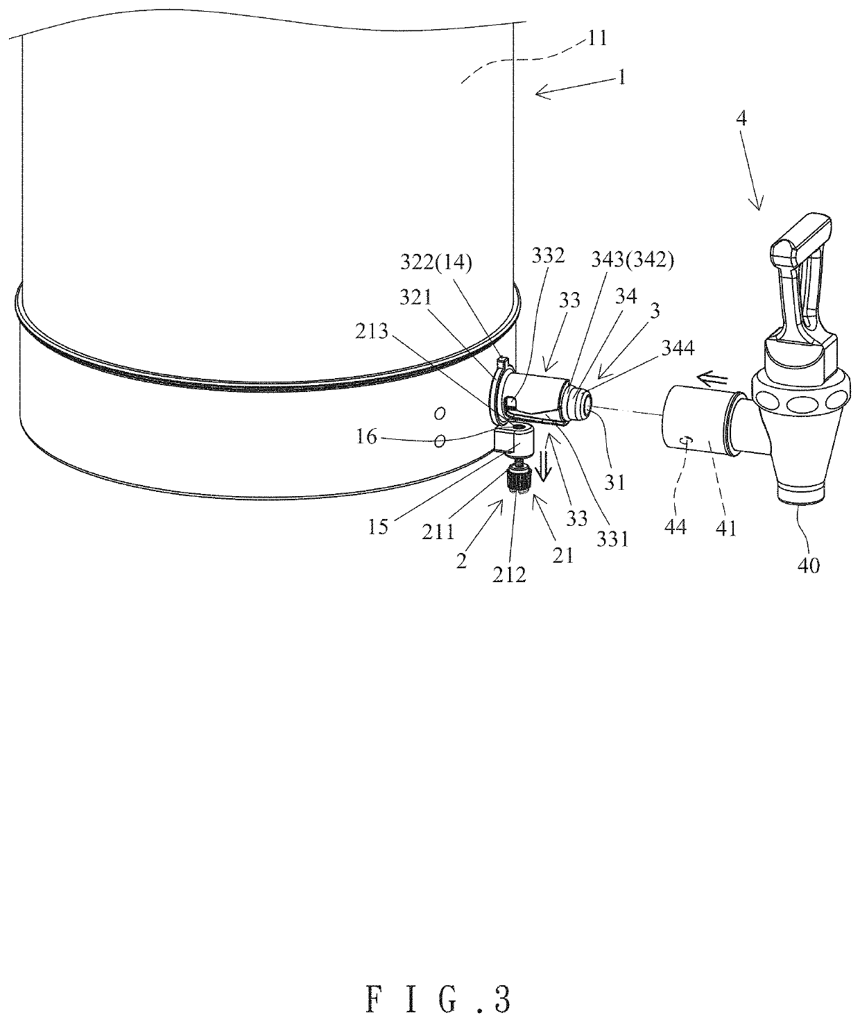
[0026]With reference to FIGS. 1-7, a container faucet assembly of an embodiment according to the present invention includes a container 1, a locking device 2, a connecting device 3, and a faucet 4. In this embodiment, the direction in which the container 1 faces the faucet 4 is the front direction. The container 1 includes a compartment 11 and an engaging portion 12. The engaging portion 12 of the container 1 includes an engaging hole 13 and a protrusion 15. A positioning groove 14 is defined in an upper portion of an inner periphery of the engaging hole 13. The protrusion 15 is disposed adjacent to a peripheral edge of the engaging hole 13 and is located below the engaging hole 13 in this embodiment. A through bore 16 extends through the protrusion 15 in a direction perpendicular to an extending direction of the engaging hole 13.

[0027]The locking device 2 includes a locking knob 21 and an elastic element 22. An insertion section 211 extends from a side of the locking knob 21 and ex...


PUM


Abstract

A container faucet assembly includes a locking device disposed on a container and having a locking knob. A tubular member has a through-hole, an insertion section, a coupling section, and a front section. The insertion section is coupled with the container. The coupling section includes an outer periphery having at least one guiding groove with a transverse section. A seal is disposed around the front section. The faucet further includes a coupling portion having a coupling hole intercommunicating with an outlet of the faucet. An inner periphery of the coupling hole includes at least one protrusion slidably received in the at least one guiding groove. A radial hole extends through the inner periphery of the coupling hole and intercommunicates with the coupling hole. A locking end of the locking knob extends into the radial hole. A sealing portion is disposed on the inner periphery of the coupling hole.

Description

BACKGROUND OF THE INVENTION[0001]The present invention relates to a container faucet assembly and, more particularly, to a container faucet assembly with improved assembling convenience and a stable structure.[0002]A type of container includes a faucet at a lower end thereof to permit dispensing of a liquid in the container without moving the container. The liquid in the container can be a beverage, such as tea, coffee, fruit juice, etc. The faucet can be detached from the container to allow easy cleaning and easy sanitary maintenance.[0003]FIGS. 8 and 9 show a conventional faucet assembly for a container 1′. The faucet assembly includes a faucet 3′ and a connecting device 2′ disposed on the container 1′. The connecting device 2′ includes a tube 21′ and a knob 22′. The tube 21′ includes a rear end coupled to an outlet 11′ of the container 1′ and a front end with a first conical face 211′. The tube 21′ further includes an abutting portion 212′ on an outer periphery thereof. The knob ...

Claims


Application Information

Patent Timeline
Patent Type & Authority Patents(United States)
IPC IPC(8): B67D3/00B67D3/04
CPCB67D3/045B67D3/04
Inventor LIN, YEN-LIN
Owner LIN YEN LIN
Learn More