Knee supporter
a supporter and knee technology, applied in the field of knee supporters, can solve the problems of rash on the skin, inconvenient use, and inability to meet the needs of patients, and achieve the effects of reducing the burden on the knee region of the wearer, facilitating movement, and ensuring stability
- Summary
- Abstract
- Description
- Claims
- Application Information
AI Technical Summary
Benefits of technology
Problems solved by technology
Method used
Image
Examples
first embodiment
of the Present Invention
[0067]In the present invention, a bandage means a“thing which includes a band-shaped fabric having stretchability in a warp direction as a main material and in which the band-shaped fabric is wound around a part of the body, thereby being able to assist a function of the body”, and as long as it has such an effect, even if it is not expressed as a bandage (for example, a taping supporter, a supporter band, or the like), it is within the scope of the bandage according to the present invention.
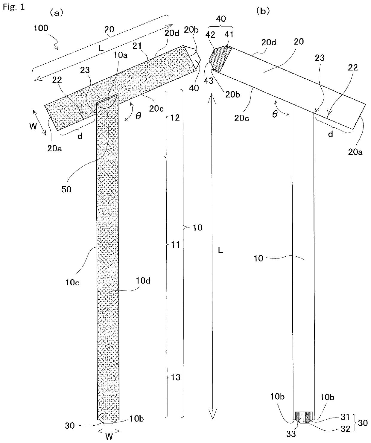
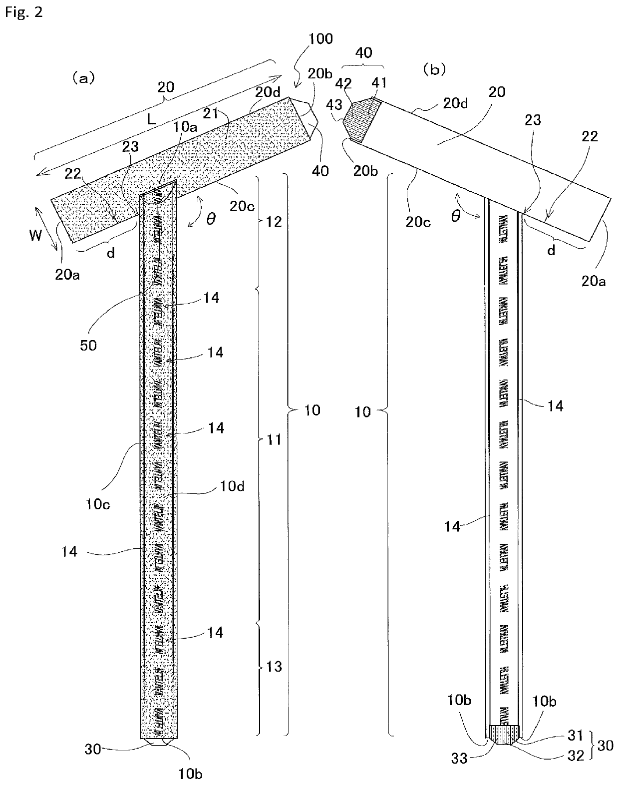
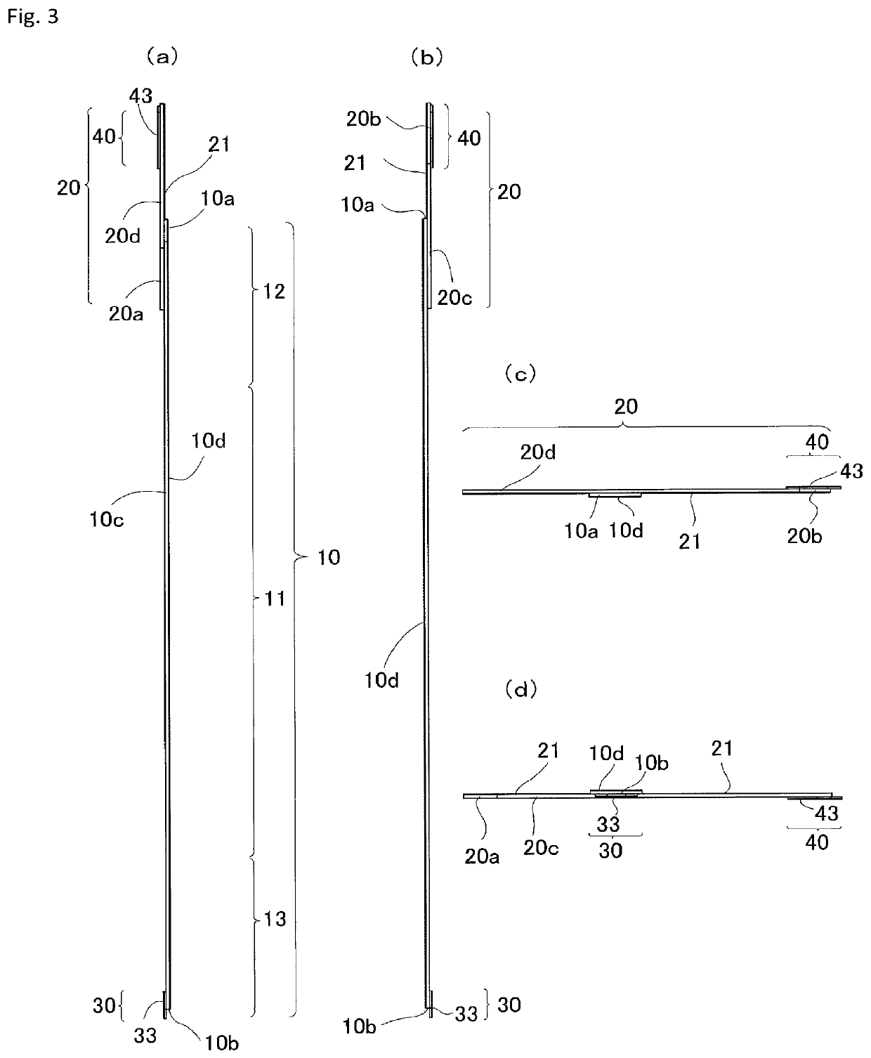
[0068]A knee joint bandage 100 according to the present invention comprises: a main body part 10 which is woven in a fabric having a loop face 10d of a touch fastener and is composed of a winding part 11 which is wound around the lower leg of a wearer, a first supporting part 12 which is disposed in a taut state on one side of a part corresponding to the patella of the wearer, and a second supporting part 13 which is disposed in a taut state on the other side of the part ...
second embodiment
of the Present Invention
[0184]FIG. 11(a) is a front view showing a schematic configuration of a knee joint bandage according to a second embodiment, and FIG. 11(b) is a back view of the knee joint bandage shown in FIG. 11(a). FIG. 12(a) is a left side view of the knee joint bandage shown in FIG. 11(a), FIG. 12(b) is aright side view of the knee joint bandage shown in FIG. 11(a), FIG. 12(c) is a plan view of the knee joint bandage shown in FIG. 11(a), and FIG. 12(d) is a bottom view of the knee joint bandage shown in FIG. 11(a). FIG. 13(a) is an explanatory diagram of the wearing state of the knee joint bandage shown in FIGS. 11 and 12 when viewed from the right side, FIG. 13(b) is an explanatory diagram of the wearing state of the knee joint bandage shown in FIGS. 11 and 12 when viewed from the front side, FIG. 13(c) is an explanatory diagram of the wearing state of the knee joint bandage shown in FIGS. 11 and 12 when viewed from the back side, and FIG. 13(d) is an explanatory diagr...
third embodiment
of the Present Invention
[0196]FIG. 14(a) is a front view showing a schematic configuration of a knee joint supporter according to a third embodiment, and FIG. 14(b) is a back view of the knee joint supporter shown in FIG. 14(a). FIG. 15(a) is an explanatory diagram showing a state where a first anchor part of the knee joint supporter shown in FIG. 14 is fastened around the thigh, FIG. 15(b) is an explanatory diagram showing a state where a third engaging part of a first supporting part of the knee joint supporter shown in FIG. 14 is engaged with the first anchor part, FIG. 15(c) is an explanatory diagram showing a state where a first engaging part of a second supporting part of the knee joint supporter shown in FIG. 14 is engaged with the first anchor part, and FIG. 15(d) is an explanatory diagram of the wearing state of the knee joint supporter shown in FIG. 14 when viewed from the right side. FIG. 16(a) is an explanatory diagram for describing an example of a fabric weave of a fro...
PUM
 Abstract
Description
Claims
Application Information
 - R&D
- Intellectual Property
- Life Sciences
- Materials
- Tech Scout
- Unparalleled Data Quality
- Higher Quality Content
- 60% Fewer Hallucinations
Browse by: Latest US Patents, China's latest patents, Technical Efficacy Thesaurus, Application Domain, Technology Topic, Popular Technical Reports.
© 2025 PatSnap. All rights reserved.Legal|Privacy policy|Modern Slavery Act Transparency Statement|Sitemap|About US| Contact US: help@patsnap.com


