Method and system of timing and localizing a radio signal

a radio signal and timing technology, applied in the field of method and system of timing and localizing a radio signal, can solve the problems of not being suited to the low-power range segment of the iot, considerable computing power, and still difficult indoor reception

Active Publication Date: 2020-08-18
SEMTECH CORP
View PDF28 Cites 0 Cited by
  • Summary
  • Abstract
  • Description
  • Claims
  • Application Information

AI Technical Summary

Benefits of technology

[0043]The end of the detect sequence is marked by one or more, preferably two, frame synchronization symbols 412 that are chirps modulated with predetermined values, for example a first chirp with a modulation value of 4, and a second one with the opposite modulation N−4. Preferably, the modulation of the frame synchronization symbols is larger, in absolute shift, than three units to minimize the likelihood of errors. The use of a single modulated symbol as frame synch marker or of the same modulation value for several symbols are also possible, but not optimal.Frequency Synchronization
[0045]While the clocks 576 of the receivers sport excellent precision and stability, the mobile nodes 510 tend to be low-cost devices and are equipped with inferior clocks, whose frequency can drift due to changes in temperature, aging, driving level, and many other perturbing factors. Slight frequency drifts do not necessarily inhibit demodulation of the LoRa signals. They may increase the error rate, however, and have a very negative influence on ranging and localization. For these reasons, the receivers 521-524 are preferably arranged for determining and modelling the frequency drift of the transmitter from the received signal.
[0051]A first operation that improves timing is fine timing drift compensation. As already mentioned, the frequencies of the transmitter's time base and of the receiver's one are not perfectly the same, and the frequency synchronization explained above allows estimating the amount of error. This can be corrected for improved accuracy. When the timing of the signal is extracted by way of dechirping, frequency drift can be compensated by adjusting slopes, initial frequency, and phase of the conjugate chirp that is synthesized locally. The chirp slope adjustment is proportional to the estimated frequency error, and can be constant for all symbols or, if needed, adapted for each symbol. The chirp initial frequency is offset by an amount that is proportional to the accumulated timing error that is increased progressively at each symbol by a step that is proportionally to the estimated frequency error. Lastly, the phase can be adjusted, such that the inter-symbol phase continuity is preserved. Since LoRa preamble signals are relatively long, (up to 250 ms), timing drift compensation allows coherent processing of the whole preamble, or at least of a large part of it, and helps improving the timing precision.
[0063]It has been found advantageous to use only a part of the available bandwidth to compute the timestamp in condition of multipath. The reason of this apparent contradiction is that, when multipath severely degrades the reception, there often is a destructive interference between competing paths. In this situation, there will be a frequency fd (see FIG. 8) in the bandwidth at which the signal almost exactly cancels. The channel response is smooth and exhibits a low derivative absolute value, because the signal bandwidth is lower than the channel coherence bandwidth. Therefore, when the channel response amplitude is close to zero, its phase essentially switches sign at this frequency. The effect is to reduce and potentially cancel completely the inner product: the portion above this frequency will he in phase opposition to the portion below.
[0068]A possible multipath discrimination process can be outlined as follows: For each sub-band 415a-c a timing process is performed, and the interpolation step provides, for each sub-band, an estimate of the position and of the amplitude of the correlation peak. The full band is processed in the same manner and amplitude and position for the full-band correlation peak are obtained as well. Since sub-band inner products are partial sums of the complete inner product, the latter can be obtained directly from the sub-band inner products without iterating on the vector factors again. Therefore, full amplitude and position can be computed at the only extra cost of one interpolation which, in terms of complexity, is much less demanding. To make a comparison on a real example, interpolation from 3 points works well with a parabolic fit, which takes a few tens of real valued multiplications. The inner products for the full band can take as much as 3 vectors×8 symbols×4096 samples≈100'000 complex valued multiplications and addition, i.e. 400'000 real valued complex multiplications plus 200'000 real valued additions. Therefore, the addition of the sub-band analysis contributes negligibly to the computation load.
[0069]In the absence of phase inversion within the band, the absolute interpolated amplitudes of sub-bands essentially sum up to the absolute interpolated amplitude of the full band. This is because when there is no phase inversion, since the channel is slowly moving versus frequency, its phase derivative is almost constant. Then the interpolated delay corresponds to a projection vector aligned with the received signal. When a phase inversion is present, absolute amplitudes do not sum up anymore, and the sum of absolute amplitude of sub bands will be higher than the absolute amplitude of full band. The same applies to sub divisions of sub bands. This allows detecting the occurrence of such a phase inversion based on the amplitude of the received signal in the sub-bands.

Problems solved by technology

Although these systems have been extremely successful in many ways, they are not so well suited to the low-power range segment of the IoT.
In particular the initial acquisition of the signals demands a considerable computing power, and indoor reception is still very difficult.
Multipath is ever present in real communication channels and it degrade the accuracy of timing.
Therefore, the techniques derived from radar applications are not really effective for LoRa signals.
In particular, LoRa signals last much longer, and the structure of the signals does not allow resolving multipath in the time domain.
These methods, however, are computationally very intensive, particularly, in our case, where the vectors can be very long, and the number of multipath components is not known in advance.

Method used


Image

  • Method and system of timing and localizing a radio signal
  • Method and system of timing and localizing a radio signal
  • Method and system of timing and localizing a radio signal

Examples


Embodiment Construction

)

Recall of LoRa Modulation

[0025]Several aspects of the chirp modulation technique employed in the present invention are described in European Patent Applications EP2449690 and EP2767848, which are hereby incorporated by reference, and will be reminded here summarily.

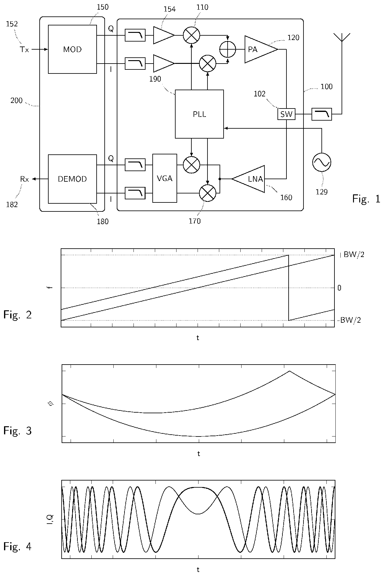
[0026]The radio transceiver that is represented schematically in FIG. 1 is part of a possible embodiment of the invention. It includes a baseband section 200 and a radiofrequency section 100. Concentrating on the transmitter part, the baseband modulator 150 generates, based on the digital data 152 that are present at its input, a baseband signal whose I and Q component are converted to the desired transmission frequency by the RF section 100 amplified by the power amplifier 120, and transmitted by the antenna. This architecture allows several variants and modifications without departing from the frame of the invention, and is a non-limiting example. For example, the transceiver could synthesize the polar components ampli...


PUM


Abstract

Method of timing, in a receiver, a radio signal generated in and transmitted from a transmitter, the radio signal comprising a series of frequency chirps, the system including: receiving the radio signal from the transmitter; synthesizing projection vectors comprising a series of frequency chirps that are a complex-conjugate image of those comprised in the radio signal the projection vectors being time-shifted relative to one another by determined shift intervals of time; multiplying the received radio signal by the projection vectors and accumulating the results; interpolating the accumulating results to determine a peak time shift.

Description

REFERENCE DATA[0001]The present application claims priority from European Patent Application EP16180271.5 of Jul. 20, 2016, the contents whereof are incorporated by reference in their entirety.FIELD OF THE INVENTION[0002]The present invention relates, in embodiments, with systems and methods for determining with precision the time of arrival (TOA) of a radio signal to a receiver and, by combining precise determinations of the time of arrival at different sites, the localization of the radio transmitter.BACKGROUND[0003]Thanks to the recent improvements in microelectronics and communication systems, a large number of devices and objects have been embedded with electronics, software sensor, and connectivity means that allow them to collect and exchange information. This network of objects, is called the Internet of Things, or IoT.[0004]IoT objects are often simple devices with modest energy resources, as they must rely on local accumulators or energy harvesting. They need therefore wir...

Claims


Application Information

Patent Timeline
Patent Type & Authority Patents(United States)
IPC IPC(8): G01S5/06G01S11/02G01S5/02H04B1/69
CPCG01S5/06G01S5/0221H04B1/69G01S11/026H04B2001/6912G01S5/02216H04L27/103H04L5/003
Inventor SELLER, OLIVIER BERNARD ANDRÉ
Owner SEMTECH CORP
Why Eureka
Try Eureka