Viewing device for vehicle

a technology for viewing devices and vehicles, applied in the field of vehicle viewing devices, can solve problems such as inability strange feeling, and small objects, and achieve the effects of not being able to view objects of concern, and being unable to view objects

Active Publication Date: 2020-08-11
TOYOTA JIDOSHA KK
View PDF42 Cites 3 Cited by
  • Summary
  • Abstract
  • Description
  • Claims
  • Application Information

AI Technical Summary

Benefits of technology

[0005]In consideration of the above circumstances, an object of the present disclosure is to provide a viewing device for a vehicle that may moderate a feeling of strangeness during viewing and that may change a display range.
[0012]In the viewing device for a vehicle described above, the meaning of the term “vehicle structural member” includes, for example, structural objects such as pillars, the roof and so forth. According to the viewing device for a vehicle of the third aspect, even when the viewing image that is displayed is similar to the viewing image of a conventional optical mirror, because vehicle structural members that would obstruct the field of view are made translucent, objects in the vehicle surroundings can be easily viewed even while the feeling of strangeness associated with an electronic mirror is moderated.
[0014]In the viewing device for a vehicle described above, the image of the vehicle occupant on the rear seat is composited in an opaque state. According to the viewing device for a vehicle of the fourth aspect, because the vehicle occupant on the rear seat is made visible, the condition of the vehicle occupant may be checked and communication may be facilitated.
[0016]In the viewing device for a vehicle described above, when a viewing image of the vehicle rear is being generated, the operation component being operated toward the near side, which is the side thereof at which the driver is disposed, switches the viewing image such that the viewing range expands to the vehicle front side, which is the side at which the driver is disposed. Thus, the operation direction of the operation component and the movement direction of the viewing image match up. Therefore, according to the viewing device for a vehicle of the fifth aspect, the driver may switch the viewing image intuitively.
[0021]According to the present disclosure, a viewing device for a vehicle may be provided that may moderate a feeling of strangeness during viewing and that may change a display range.

Problems solved by technology

However, although the image display device of JP-A No. 2013-141120 has the advantage of providing a view spanning rear surroundings in a wide-angle rear image composited from the plural cameras without obstruction by rear seat vehicle occupants, vehicle structural members and the like, differences from the display of a conventional optical inner mirror (below referred to simply as an optical mirror) may cause a feeling of strangeness.
Moreover, whereas the display range of the vehicle rear by the image display device is wide, objects may appear small, and it may not be possible to view objects of concern.

Method used


Image

  • Viewing device for vehicle
  • Viewing device for vehicle
  • Viewing device for vehicle

Examples


first exemplary embodiment

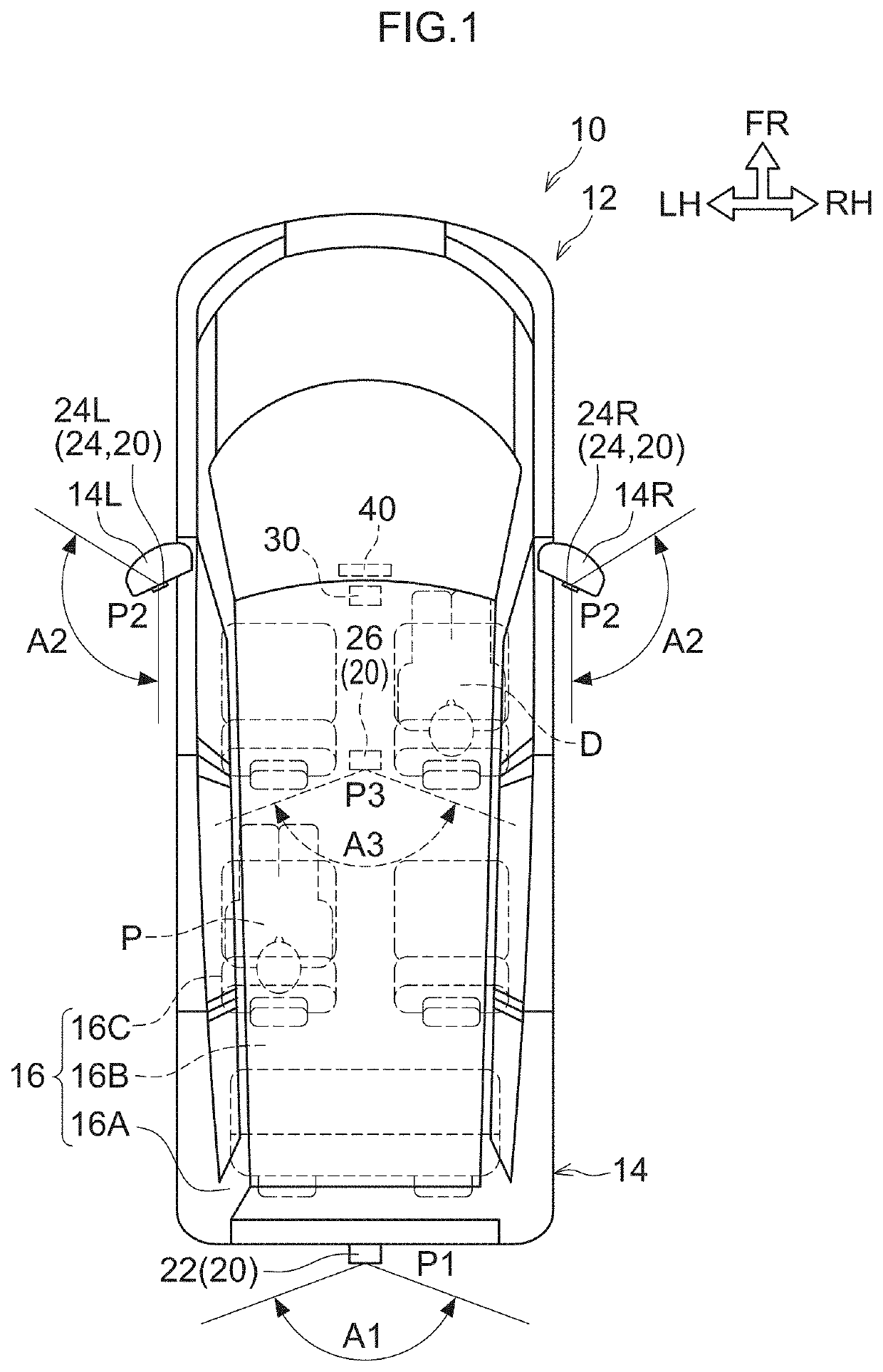
[0038]Herebelow, a first exemplary embodiment of the present disclosure is described in detail with reference to the attached drawings. FIG. 1 is a diagram showing a vehicle 12 in which a viewing device for a vehicle 10 according to the present exemplary embodiment is employed. The vehicle 12 according to the present exemplary embodiment is a vehicle in which three rows of seats are arranged in the vehicle front-and-rear direction, such as a minivan, a people-mover or the like. Note, however, that FIG. 1 and FIG. 4A to FIG. 6C show an example in which a driver D is seated and in which a passenger P is seated at the left side of rear seats 16C (in the second row).

[0039]—Structures—

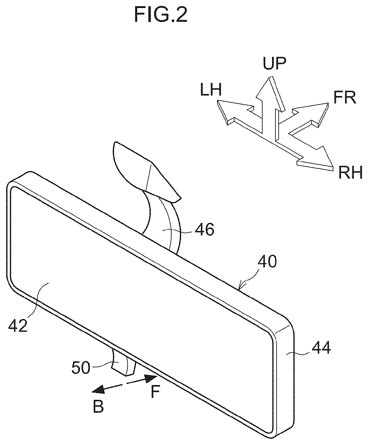
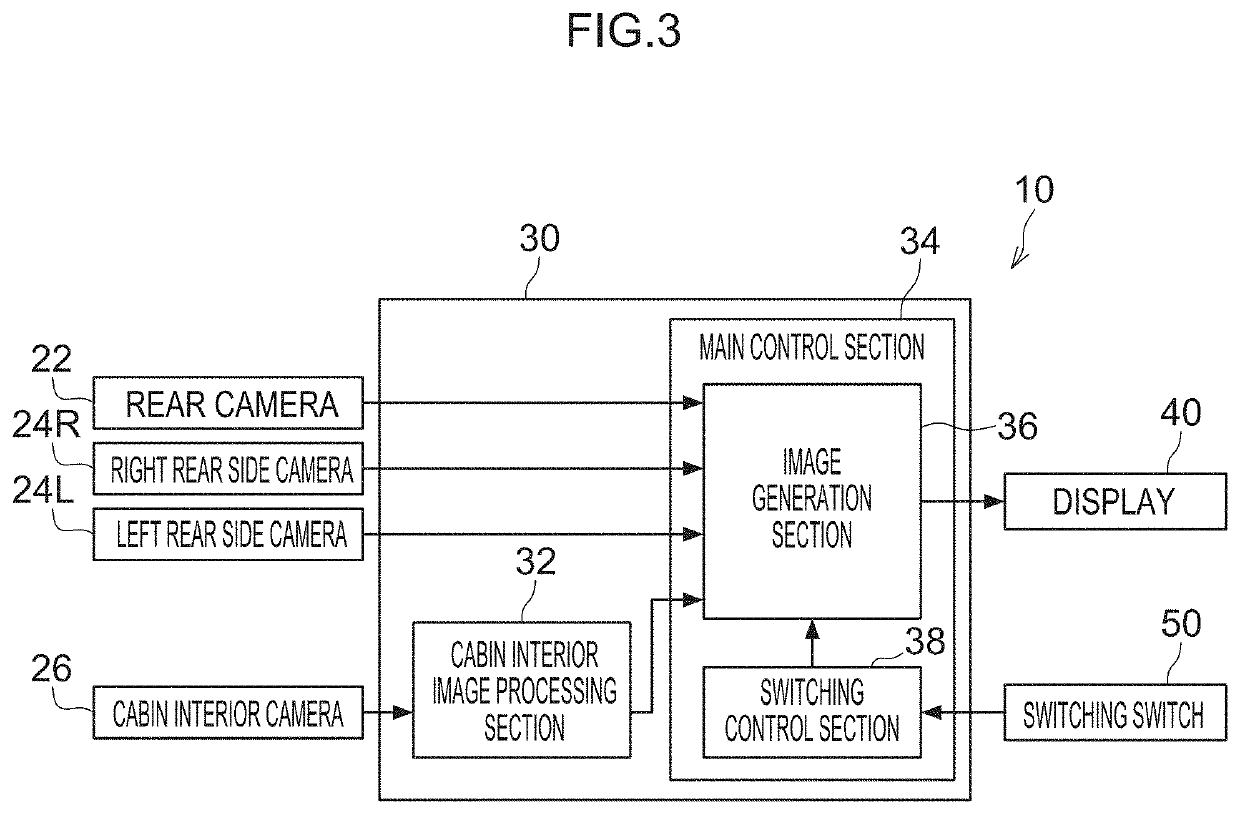
[0040]As shown in FIG. 1 to FIG. 3, the viewing device for a vehicle 10 according to the present exemplary embodiment includes plural cameras 20, a display 40, a switching switch 50 and a control device 30. These structures are described below.

[0041]The viewing device for a vehicle 10 according to the prese...

second exemplary embodiment

[0113]In the viewing device for a vehicle 10 according to the first exemplary embodiment, the viewing image is switched in accordance with operations of the switching switch 50. In contrast, in the viewing device for a vehicle 10 according to a second exemplary embodiment, the switching control section 38 may switch the viewing image in accordance with information on objects that are present in the viewing ranges of the cameras 20. To be specific, in the present exemplary embodiment, an object detection sensor 52 is provided instead of the switching switch 50 according to the first exemplary embodiment, and signals from the object detection sensor 52 are inputted to the switching control section 38.

[0114]The object detection sensor 52 according to the present exemplary embodiment is a millimeter wave radar, an ultrasound sonar or the like, which may detect positions and movement speeds of objects such as vehicles, pedestrians, obstacles on the road and the like in the surroundings o...

third exemplary embodiment

[0117]The viewing device for a vehicle 10 according to the first exemplary embodiment switches the viewing image in accordance with operations of the switching switch 50, and the viewing device for a vehicle 10 according to the second exemplary embodiment switches the viewing image in accordance with information from the object detection sensor 52. In contrast, in the viewing device for a vehicle 10 according to a third exemplary embodiment, the switching control section 38 may switch the viewing image in accordance with the eyeline of a driver D. To be specific, in the present exemplary embodiment, an eye tracker 56 is provided instead of the switching switch 50 of the first exemplary embodiment, and signals from the eye tracker 56 are inputted to the switching control section 38.

[0118]The eye tracker 56 according to the present exemplary embodiment is configured to be able to detect the eyeline direction of the driver D from turning movements of the pupils and changes in reflectan...


PUM


Abstract

A viewing device for a vehicle is provided with plural cameras, an image generation unit, a display and a switching control unit. The plural cameras have different imaging ranges. On the basis of captured images from one or a plural number of the cameras, the image generation unit generates plural viewing images that differ in at least one of viewpoint or viewing angle. The display displays the viewing images. The switching control unit is capable of switching a viewing image being displayed at the display to another of the viewing images.

Description

CROSS-REFERENCE TO RELATED APPLICATION[0001]This application is based on and claims priority under 35 USC 119 from Japanese Patent Application No. 2017-060179 filed on Mar. 24, 2017, the disclosure of which is incorporated by reference herein.BACKGROUNDTechnical Field[0002]The present disclosure relates to a viewing device for a vehicle that displays captured images in which vehicle surroundings are imaged.Related Art[0003]Japanese Patent Application Laid-Open (JP-A) No. 2013-141120 (Patent Document 1) discloses an image display device (an electronic mirror) equipped with a rear camera that images to the rear of a vehicle and a rear side left camera and rear side right camera that image to the sides of the rear of the vehicle. In this image display device, an image captured by the rear camera is composited with images captured by the rear side left camera and the rear side right camera to generate a continuous rear image. Thus, objects disposed to the rear of the vehicle can be disp...

Claims


Application Information

Patent Timeline
Patent Type & Authority Patents(United States)
IPC IPC(8): H04N5/247G06T19/00H04N5/268B60R1/00B60R1/04G06K9/00B60R1/12
CPCB60R1/04H04N5/247H04N5/268G06T19/006G06K9/00604B60R1/00B60R1/12G06T2207/30196B60R2300/8026B60R2300/202B60R2001/1253B60R2300/70B60R2300/303B60R2300/30G06T2207/30268B60R2300/105H04N7/181H04N7/185H04N23/60H04N23/90G06V40/19
Inventor KUMON, HITOSHITAKAHASHI, YASUNOBUOHTSUKA, YUTO
Owner TOYOTA JIDOSHA KK
Why Eureka
Try Eureka