
Flashlight

a flashlight and light source technology, applied in the field of flashlights, can solve the problems of natural offset, shadow on the target, and the target is often poorly illuminated with respect to the viewing perspectiv

Active Publication Date: 2020-08-04
HOFER STEVEN
View PDF10 Cites 0 Cited by
  • Summary
  • Abstract
  • Description
  • Claims
  • Application Information

AI Technical Summary

Benefits of technology

The present invention is a new flashlight that can be used to illuminate and view a target without creating shadows that may make it difficult to see the target. In an alternative embodiment, a lens is included in the flashlight to improve the viewing of the target.

Problems solved by technology

The problem, however, is that when the target is viewed by a user, the light source of the flashlight and the viewing perspective are naturally offset from each other.
For example, in the event the target of the light source is positioned in a tight space, or positioned behind one or more intervening objects, the target is often poorly illuminated with respect to the viewing perspective.
Although the conventional flashlight provides some light directed at the target, the intervening objects will cause a shadow on the target.
In addition to conventional flashlights failing to provide a channel for viewing the target, these devices also fail to include a shoulder adapted to minimize ambient light and light emitted from the one or more light sources from entering the channel.
Allowing light to enter the channel from which a user is viewing obstructs vision and reduces the overall efficacy of the flashlight.

Method used


Image

  • Flashlight
  • Flashlight

Examples


Embodiment Construction

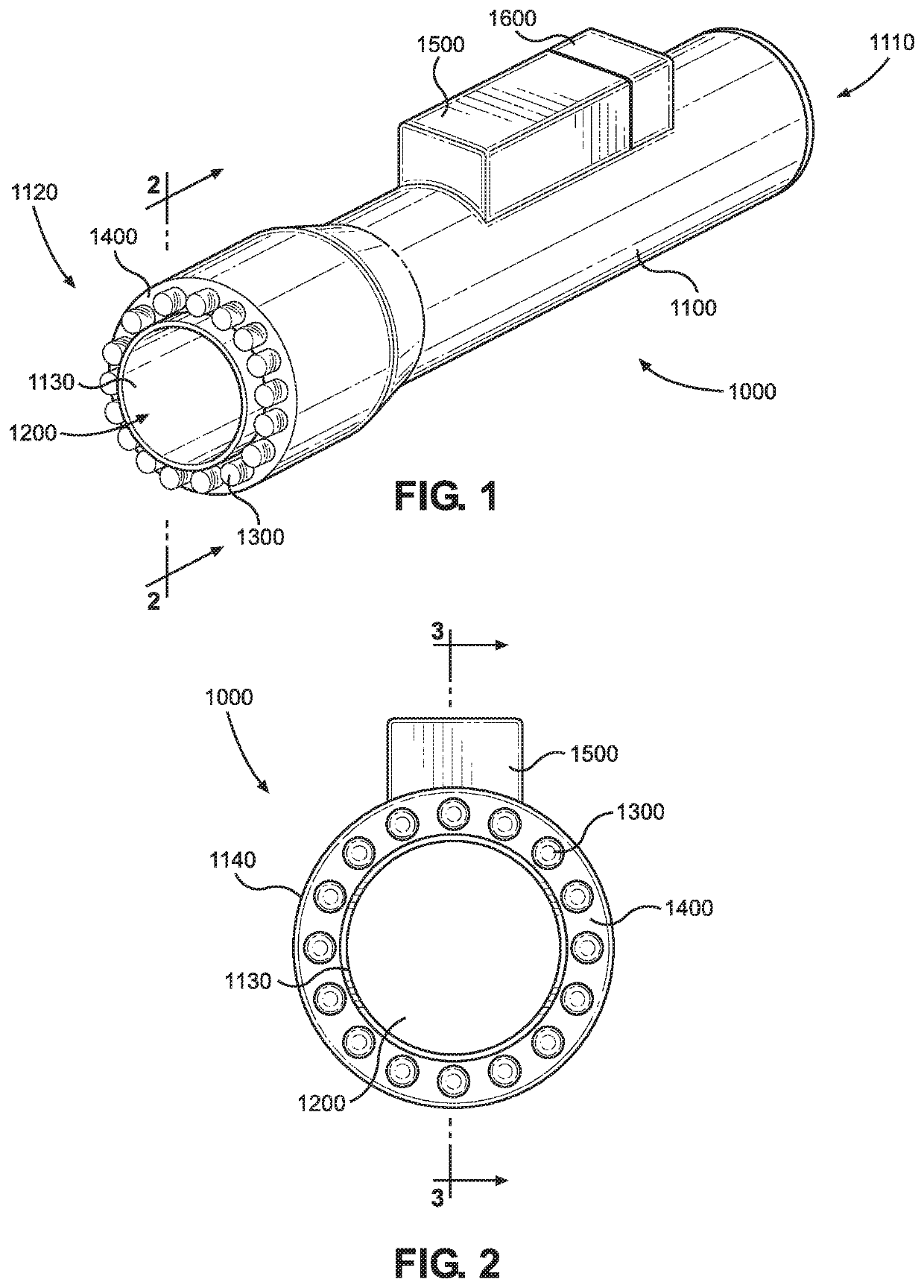
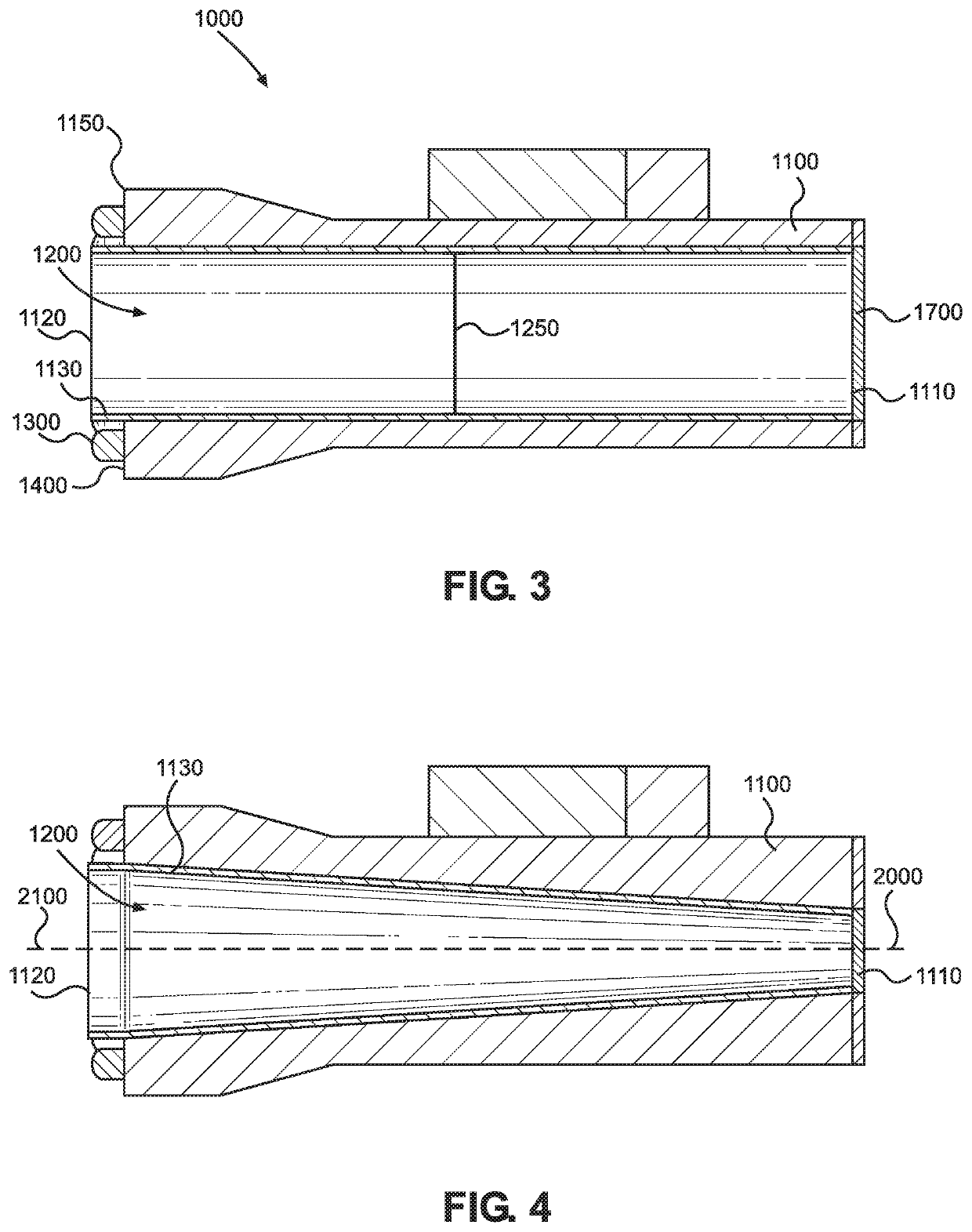
[0018]Reference is made herein to the attached drawings. Like reference numerals are used throughout the drawings to depict like or similar elements of the flashlight. For the purposes of presenting a brief and clear description of the present invention, the preferred embodiment will be discussed as used for illuminating and viewing an object or target in a generally hard to access location, such as a behind a wall, within a conduit, or within a body of a vehicle, to illuminate the object, free from an umbra or shadow generated by the flashlight. The figures are intended for representative purposes only and should not be considered to be limiting in any respect.

[0019]Referring now to FIGS. 1 and 2, there is shown a view of a first embodiment of the flashlight and a front-end view of the first embodiment of the flashlight as viewed from line 2-2 of FIG. 1, respectively. The flashlight 1000 provides a device that is selectively activated and targeted to an object for illumination. The...


PUM


Abstract

A flashlight for the illumination of an object and viewing the object through the flashlight. The flashlight includes a housing having an inner side forming a channel that extends between a first end of the housing and a second end of the housing. The flashlight includes one or more light sources that are able to emit light therefrom and at a desired target. A power supply is operably connected to a control such that they operate the one or more lights. The inner side of the housing extends past a forwardmost edge of an outer side of the housing at the second end to form a shoulder. The shoulder extends about the housing and, in one embodiment, the one or more lights are disposed thereon. In this way, the one or more lights directly illuminate a target without causing shadows to form from the viewing perspective.

Description

BACKGROUND OF THE INVENTION[0001]The present invention relates to a flashlight. More specifically, the present invention relates to a flashlight having a channel extending therethrough that provides a viewing perspective of a target.[0002]Conventional flashlights are designed to be powered by batteries installed within a barrel of the flashlight rearwardly of the light source. This placement of the batteries with respect to the light source, generally forms an enclosed housing that can be handled and the light source directed as desired. The problem, however, is that when the target is viewed by a user, the light source of the flashlight and the viewing perspective are naturally offset from each other. For example, in the event the target of the light source is positioned in a tight space, or positioned behind one or more intervening objects, the target is often poorly illuminated with respect to the viewing perspective. Although the conventional flashlight provides some light direc...

Claims


Application Information

Patent Timeline
Patent Type & Authority Patents(United States)
IPC IPC(8): F41G1/34F21V5/00F21L4/02F21V15/01F21L4/00F21V23/04F21V23/02F21Y103/33F21Y115/10
CPCF21V15/01F21V23/0414F21V5/006F21V23/02F21L4/005F21L4/027F21Y2115/10F21Y2103/33
Inventor HOFER, STEVEN
Owner HOFER STEVEN
Learn More