
Assist grip

a technology of a grip and a handle, applied in the direction of vehicle components, vehicle arrangement, transportation and packaging, etc., can solve the problems of difficult formation of thin wall portions and difficult formation of thick wall portions on the outer course side, and achieve the effect of excelling in appearance characteristics

Active Publication Date: 2021-04-20
NIFCO INC
View PDF13 Cites 0 Cited by
  • Summary
  • Abstract
  • Description
  • Claims
  • Application Information

AI Technical Summary

Benefits of technology

The present invention provides a holding tool with improved appearance, while in non-use state, the tool is difficult to view. The invention also provides a storage portion with thick walls and a hollow space, which reduces the amount of resin used and allows for weight reduction while maintaining rigidity. Additionally, the invention includes an inclined face that guides the molten resin to form the thick walls and allows for the easy creation of a hollow space.

Problems solved by technology

As a result, the thin wall portion can be difficult to be formed on the aforementioned inner course side, and the thick wall portion can be difficult to be formed on an outer course side.

Method used


Image

  • Assist grip
  • Assist grip
  • Assist grip

Examples


Embodiment Construction

[0032]Hereinafter, an embodiment of the present invention will be explained with reference to drawings. In the explanation, after an overall structure of an assist grip is clarified, essential parts and features of the device of a gas assist molding method will be described.

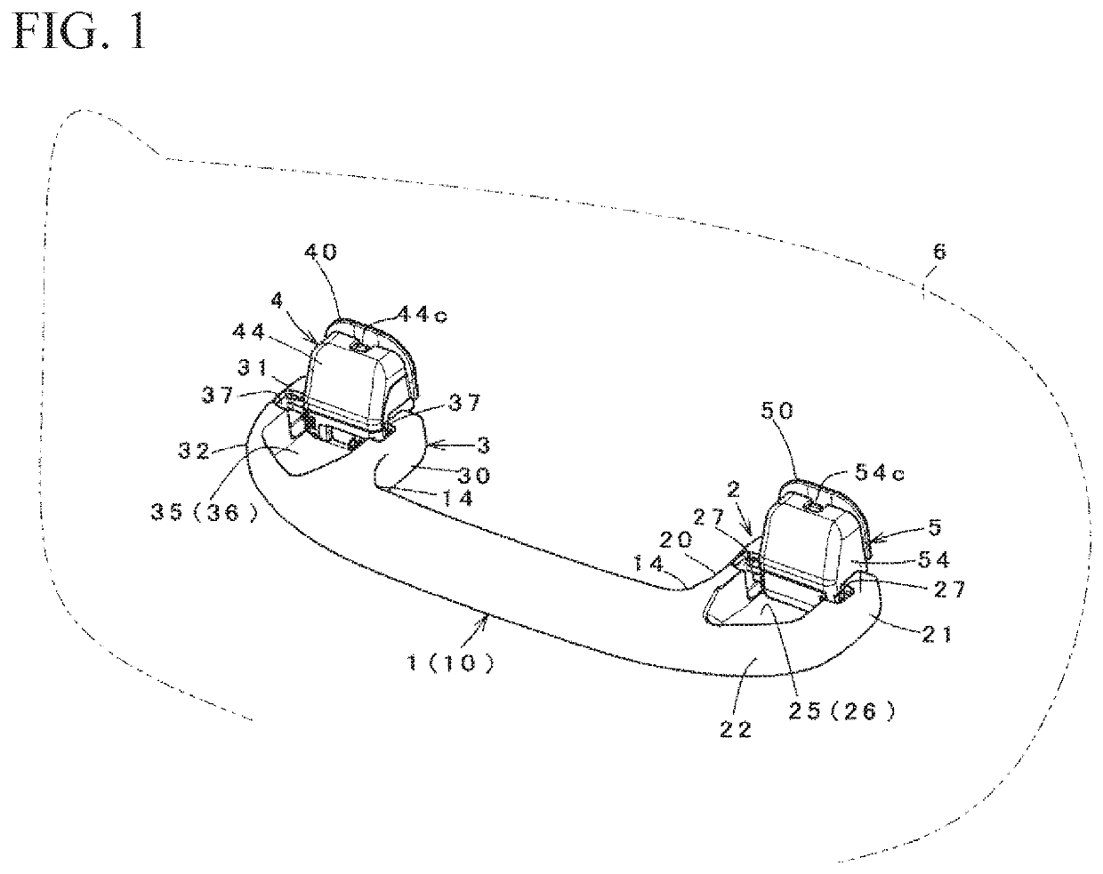
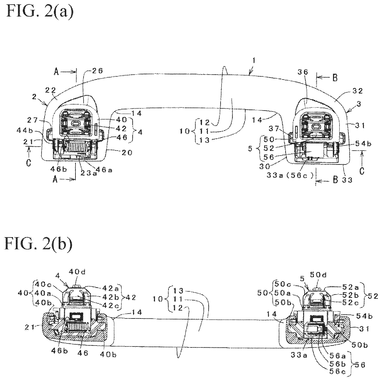
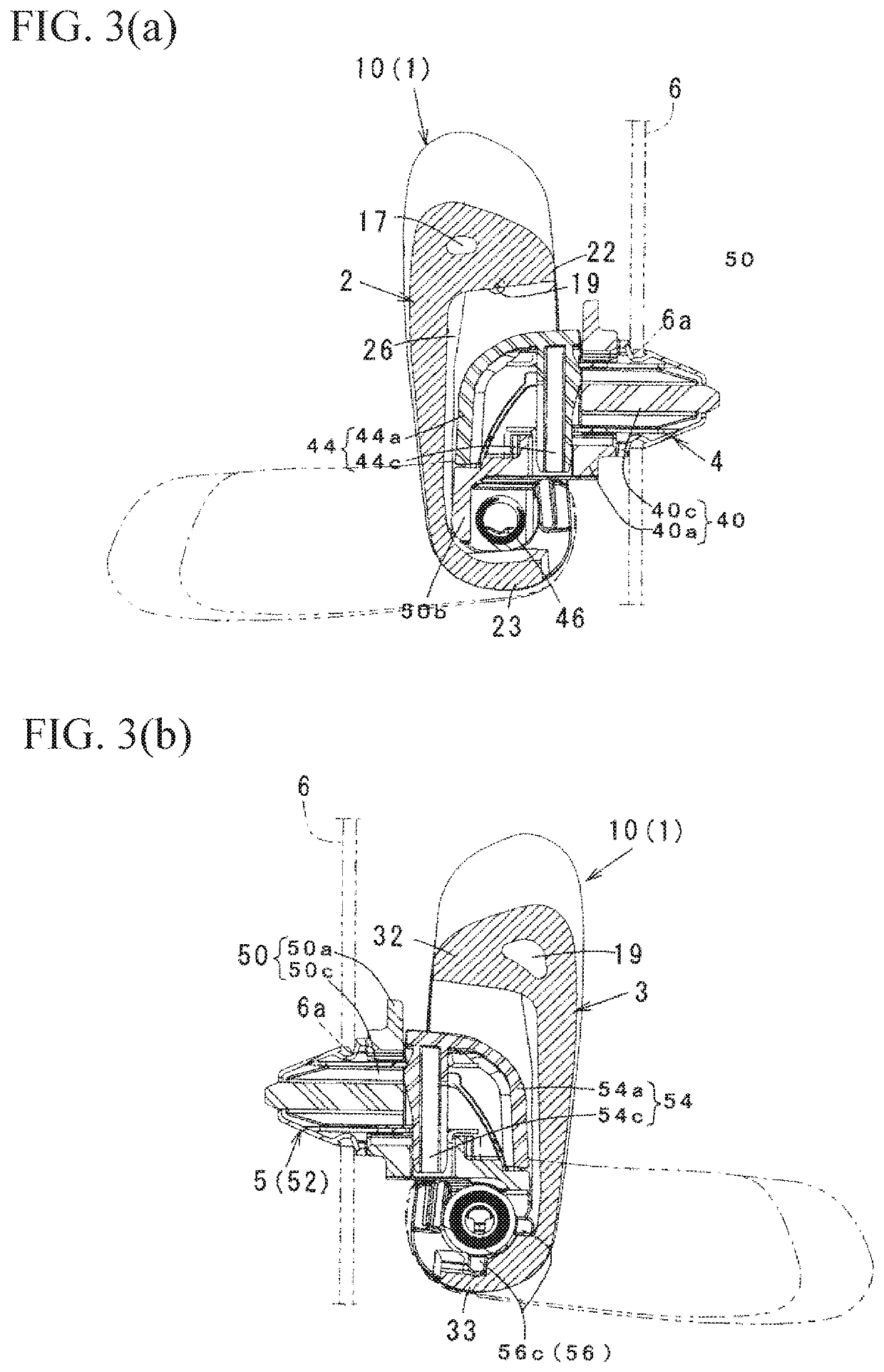
[0033](Overall structure) As shown in FIG. 1 to FIG. 3(b), the assist grip of the embodiment comprises a grip main member 1 integrally including a holding portion 10, and concave storage portions 2 and 3 provided to be connected to both ends of the holding portion 10 through curved portions 14; and holding tools 4 and 5 turnably supported in the respective storage portions 2 and 3, and the assist grip is attached relative to an attachment face 6 on an auto body side by the holding tools 4 and 5. Also, the storage portions 2 and 3 have different detailed shapes, and are asymmetric. The holding tools 4 and 5 are the same in terms of comprising holding members 40 and 50, clips 42 and 52 attached to the holding membe...


PUM


Abstract

An assist grip includes a hollow molding member in which a grip main member is formed by a gas assist molding method, a holding portion, and concave storage portions provided to be connected to both longitudinal ends of the holding portion by interposing curved portions; and is attached to an attachment-face side by holding tools supported in both storage portions. Each of the storage portions is partitioned by an inner side wall and an outer side wall facing each other in a longitudinal direction; an upper wall connecting upper sides of the side walls at a curved-portion side; a lower wall connecting lower sides of the side walls at a terminal side; and a bottom wall connecting to both side walls and the upper and lower walls at an outer face side. The upper walls include inclined faces wherein inner faces on a storage-portion side are inclined toward a bottom-wall.

Description

FIELD OF TECHNOLOGY[0001]The present invention relates to an assist grip.BACKGROUND ART[0002]In the assist grip, as shown in illustrated examples in Patent Document 1 and 2, a grip main member is sometimes made as a hollow molding member in view of weight reduction, appearance characteristics, and the like. FIGS. 11(a) to 11(c) are disclosed in the Patent Document 1; the reference numeral 1 represents a forming die comprising right and left dies 1A and 1B; the reference numeral 2 represents a grip main member (an assist grip); the reference numeral 11 represents a weir; and the reference numeral 21 represents a concave portion formed by the weir 11. There, when the grip main member 2 including a curved portion (a bent portion) 23 is made by gas assist molding, injected gas passes through an inner circumferential side (an inside course) of the curved portion having a small flow resistance so as to have a tendency of generating a thin wall portion which becomes a factor lowering a str...

Claims


Application Information

Patent Timeline
Patent Type & Authority Patents(United States)
IPC IPC(8): B60N3/02
CPCB60N3/02B60N3/023
Inventor NISHIDA, RYUHEI
Owner NIFCO INC
Learn More