Automated landing solution systems and methods

a technology of automatic landing and solution, applied in the field of aircraft navigation, can solve the problem of no beacon, but the effect of a beacon

Active Publication Date: 2020-07-14
BENCHMARK ELECTRONICS INC
View PDF10 Cites 4 Cited by
  • Summary
  • Abstract
  • Description
  • Claims
  • Application Information

AI Technical Summary

Problems solved by technology

Such a beacon, however, is no more than a homing device that allow the UAV to determine a direction to the landing pad.

Method used


Image

  • Automated landing solution systems and methods
  • Automated landing solution systems and methods
  • Automated landing solution systems and methods

Examples


Embodiment Construction

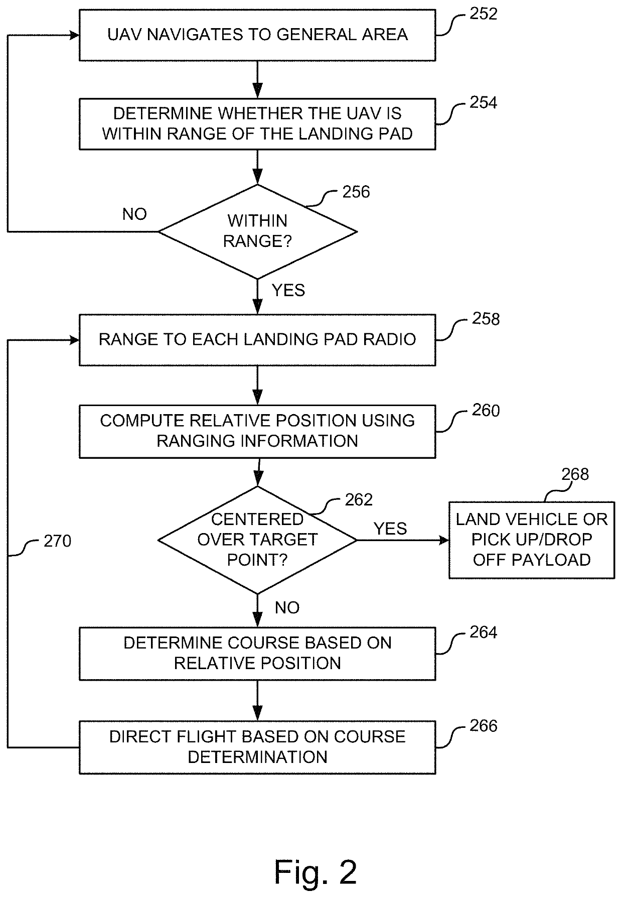
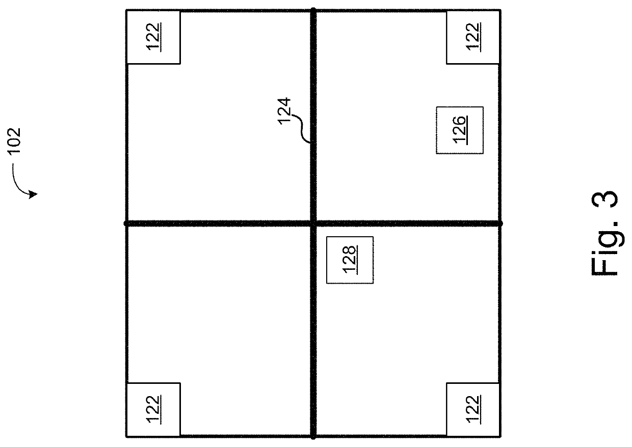
[0003]According to an embodiment of the disclosed technology A UAV landing system, includes: a landing pad defining a landing area for a UAV, the landing area comprising a target point for UAV landing or payload delivery; a plurality of positioning radios positioned in a spaced apart relation and substantially equidistant from the target point, each positioning radio of the plurality of positioning radios including a radio transmitter wherein each radio transmitter is configured to transmit a ranging signal to an approaching UAV. The UAV can include a position determination and aircraft navigation system, which may include a radio receiver to receive the ranging signals; a positioning circuit, communicatively coupled to the radio receiver, that determines a range to each positioning radio using the received ranging signals, and computes a position of the UAV relative to the target point on the landing pad; and a flight control system that determines a course for the UAV to a point a...


PUM


Abstract

A UAV landing system can include a landing pad defining a landing area including a target point; a plurality of positioning radio transmitters positioned in a spaced apart relation and equidistant from the target point, each radio transmitter transmitting a ranging signal; and a position determination and aircraft navigation system at the incoming UAV to receive the ranging signals; determine a range to each positioning radio using the received ranging signals; compute a position of the UAV relative to the target point; determine a course for the UAV to a point above the target point of the landing pad; fly the UAV to the point above the target point of the landing pad, and cause the aircraft to descend vertically toward the target point when the UAV reaches the point above the target point.

Description

TECHNICAL FIELD[0001]The disclosed technology relates generally to aircraft navigation and more particularly, some embodiments relate to an autonomous landing solution for unmanned aircraft.DESCRIPTION OF THE RELATED ART[0002]Unmanned aerial vehicles (UAVs) are growing in popularity and usage. The number of applications for UAVs has risen dramatically in recent years and it is expected to continue to increase. As the applications for UAVs rises so too has the desire for portable UAV landing pads and improved UAV landing solutions. Conventional UAV landing operations are controlled by an operator manually piloting the UAV to a safe landing using visual cues. Other systems use a beacon as a homing device that the UAV can lock on and pilot toward for landing. Such a beacon, however, is no more than a homing device that allow the UAV to determine a direction to the landing pad.BRIEF SUMMARY OF EMBODIMENTS[0003]According to an embodiment of the disclosed technology A UAV landing system, ...

Claims


Application Information

Patent Timeline
Patent Type & Authority Patents(United States)
IPC IPC(8): G08G5/00G01S1/08B64F1/00G01S3/32G05D1/06B64C27/00B64D45/04G01S5/02G08G5/02B64C39/02
CPCB64F1/00G01S5/02G01S1/08G05D1/0676B64D45/04B64C27/00B64C39/024B64C39/02G08G5/0069G08G5/02G01S3/32B64C2201/128B64C2201/141B64C2201/18B64C2201/14B64C2201/145B64C2201/108B64U2201/00B64U2201/104B64U70/00B64U2101/64B64U30/20B64U2101/60B64U2201/10
Inventor HOBBS, RONALDLUECKE, JAMES
Owner BENCHMARK ELECTRONICS INC
Why Eureka
Try Eureka