3D segmentation for robotic applications

a robotic application and 3d technology, applied in image analysis, image enhancement, programmed manipulators, etc., can solve the problem of reducing the speed at which robotic operations may be performed

Active Publication Date: 2020-06-16
ABB (SCHWEIZ) AG
View PDF8 Cites 10 Cited by
  • Summary
  • Abstract
  • Description
  • Claims
  • Application Information

AI Technical Summary

Problems solved by technology

For example, in some systems, the visual image data set for an image of a robot scene may be larger than otherwise necessary, which may necessitate the use of a more costly larger memory and / or faster processor than may otherwise be required, or may reduce the speed at which robotic operations may be performed.

Method used


Image

  • 3D segmentation for robotic applications
  • 3D segmentation for robotic applications
  • 3D segmentation for robotic applications

Examples


Embodiment Construction

[0017]For purposes of promoting an understanding of the principles of the invention, reference will now be made to the embodiments illustrated in the drawings, and specific language will be used to describe the same. It will nonetheless be understood that no limitation of the scope of the invention is intended by the illustration and description of certain embodiments of the invention. In addition, any alterations and / or modifications of the illustrated and / or described embodiment(s) are contemplated as being within the scope of the present invention. Further, any other applications of the principles of the invention, as illustrated and / or described herein, as would normally occur to one skilled in the art to which the invention pertains, are contemplated as being within the scope of the present invention.

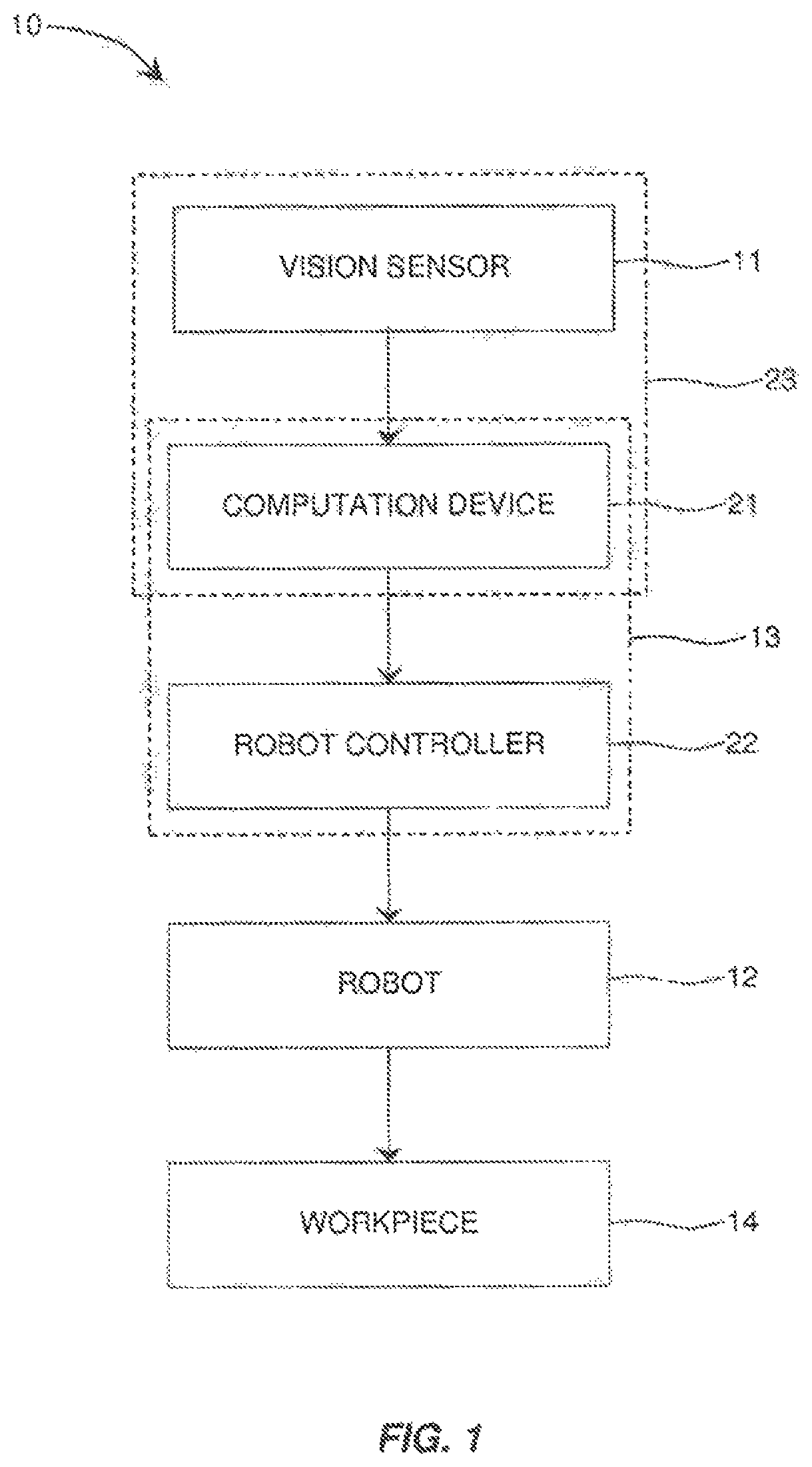
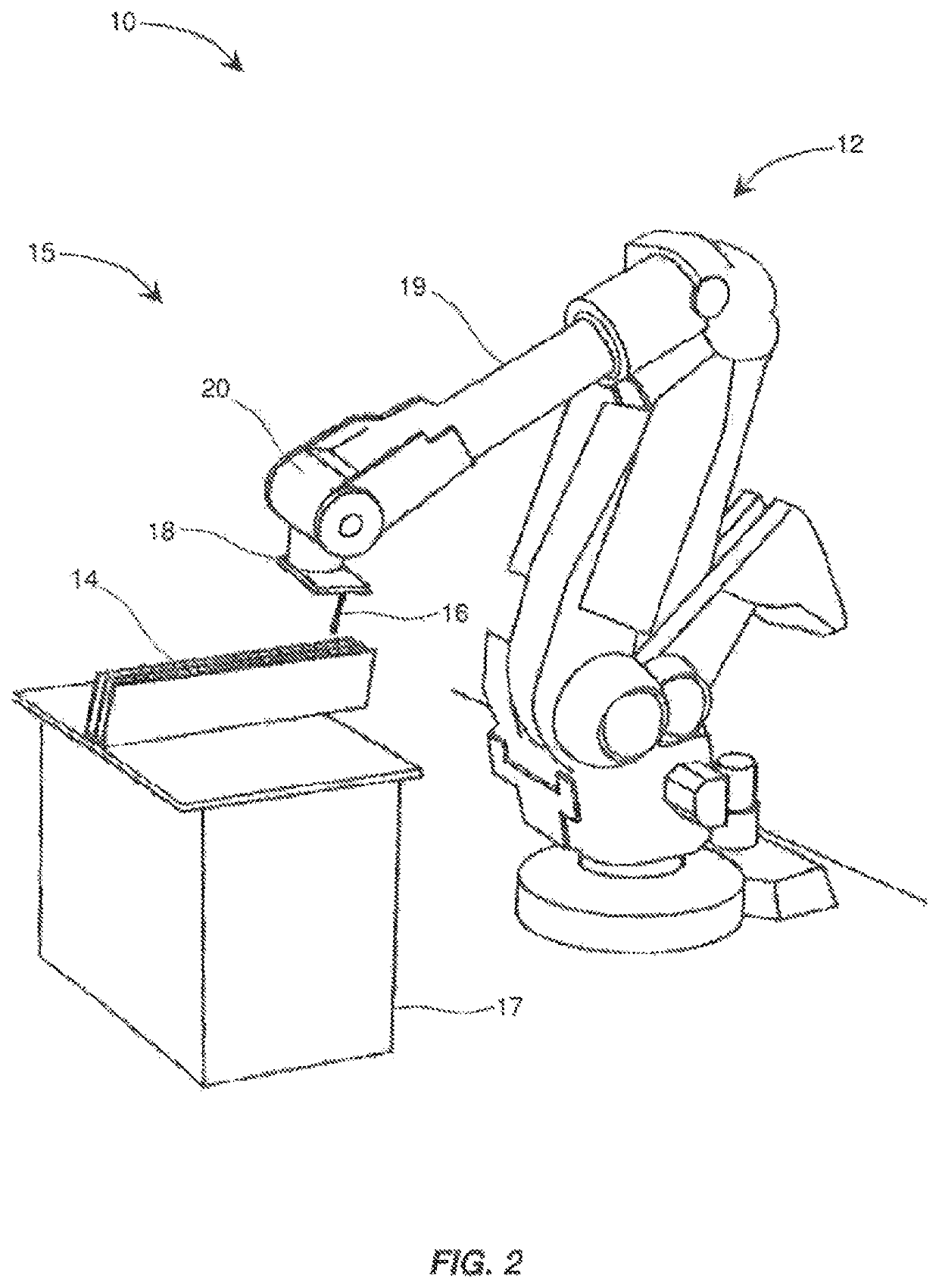
[0018]Referring to the drawings, and in particular FIGS. 1 and 2, some aspects of a nonlimiting example of a block diagram for a robotic system 10 in accordance with an embodiment ...


PUM


Abstract

A robotic system includes a robot having an associated workspace; a vision sensor constructed to obtain a 3D image of a robot scene including a workpiece located in the workspace; and a control system communicatively coupled to the vision sensor and to the robot. The control system is configured to execute program instructions to filter the image by segmenting the image into a first image portion containing substantially only a region of interest within the robot scene, and a second image portion containing the balance of the robot scene outside the region of interest; and by storing image data associated with the first image portion. The control system is operative to control movement of the robot to perform work, on the workpiece based on the image data associated with the first image portion.

Description

FIELD OF THE INVENTION[0001]This invention relates to industrial robots, and more particularly the use of 3D vision and 3D data for robotic applications.BACKGROUND[0002]Vision systems for robotic applications process image data that relates to handling a workpiece or performing a process, such as a manufacturing process, on a workpiece. Some existing systems have various shortcomings, drawbacks and disadvantages relative to certain applications. For example, in some systems, the visual image data set for an image of a robot scene may be larger than otherwise necessary, which may necessitate the use of a more costly larger memory and / or faster processor than may otherwise be required, or may reduce the speed at which robotic operations may be performed. Accordingly, there remains a need for further contributions in this area of technology.SUMMARY OF THE INVENTION[0003]Embodiments of the present invention include a robotic system. The robotic system includes a robot having an associat...

Claims


Application Information

Patent Timeline
Patent Type & Authority Patents(United States)
IPC IPC(8): G06T7/11B25J9/16G06T7/194
CPCG06T7/11B25J9/1697G06T7/194G06T2207/20168G06T2207/20104G06T2207/20121G05B2219/40004G05B2219/37555
Inventor BOCA, REMUSFUHLBRIGGE, THOMAS A.
Owner ABB (SCHWEIZ) AG
Why Eureka
Try Eureka