
Map-centric map matching method and apparatus

a map matching and map technology, applied in the field of mapcentric map matching methods and apparatuses, can solve the problems of map matching, computationally expensive spatial searches, and substantial execution time and cost, and achieve the effects of less processing capacity, reduced or eliminating latency in map matching, and improved efficiency

Active Publication Date: 2020-06-09
HERE GLOBAL BV
View PDF7 Cites 1 Cited by
  • Summary
  • Abstract
  • Description
  • Claims
  • Application Information

AI Technical Summary

Benefits of technology

This approach significantly reduces processing capacity requirements and latency in map matching, enabling faster and more efficient processing of probe data points while improving accuracy and supporting both real-time and post-processing applications.

Problems solved by technology

Spatial searches are computationally expensive.
For example, probe-centric map matching techniques for large probe data sets, such as millions of probe points, can incur substantial execution time and costs since the number of spatial searches is proportional to the number of probe points.
Thus, map matching and, in particular, the spatial searches for each of the probe points may become a limiting factor at least for real time applications.

Method used


Image

  • Map-centric map matching method and apparatus
  • Map-centric map matching method and apparatus
  • Map-centric map matching method and apparatus

Examples


Embodiment Construction

[0023]Some embodiments of the present invention will now be described more fully hereinafter with reference to the accompanying drawings, in which some, but not all, embodiments of the invention are shown. Indeed, various embodiments of the invention may be embodied in many different forms and should not be construed as limited to the embodiments set forth herein; rather, these embodiments are provided so that this disclosure will satisfy applicable legal requirements. Like reference numerals refer to like elements throughout. As used herein, the terms “data,”“content,”“information,” and similar terms may be used interchangeably to refer to data capable of being transmitted, received and / or stored in accordance with embodiments of the present invention. Thus, use of any such terms should not be taken to limit the spirit and scope of embodiments of the present invention.

[0024]As defined herein, a “computer-readable storage medium,” which refers to a physical storage medium (e.g., vol...


PUM


Abstract

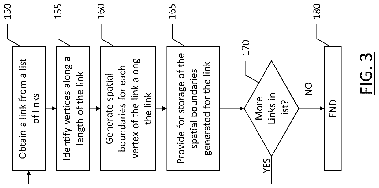
A method, apparatus and computer program product are provided to process probe data in accordance with a map-centric map matching technique. Methods may include obtaining a road link from a database of a plurality of road links; calculating a boundary separation distance for spacing vertices along a length of the road link; determining a sequence of vertices along the road link according to the boundary separation distance; generating, for each vertex, a spatial boundary where an overlap between spatial boundaries of adjacent vertices extends a first distance from the road link, where the first distance is a minimum distance from the road link; and providing for storage of a spatial boundary structure for the road link including the plurality of spatial boundaries associated with the road link.

Description

TECHNOLOGICAL FIELD[0001]An example embodiment relates generally to the map matching of probe points to a corresponding road segment as represented by a map and, more particularly, to the map matching of probe points to road segments in a map-centric manner.BACKGROUND[0002]Probe points are frequently captured by global positioning systems (“GPS”), navigation systems or the like. Each probe point is associated with a location, such as may be expressed in terms of latitude and longitude. Some probe points are also associated with a heading and a speed at which the GPS system or the navigation system was moving at the time at which the probe point was captured.[0003]In some instances, such as within a region for which a map consisting of a plurality of road segments has been created, the probe points may be matched to the map in order to identify the location along a road segment at which the probe point was captured. Map matching may be performed in real time, such as by navigation sy...

Claims


Application Information

Patent Timeline
Patent Type & Authority Patents(United States)
IPC IPC(8): G01C21/00G06F16/29G01C21/32
CPCG01C21/32G06F16/29G06F16/909G01C21/30G01C21/3867G01C21/3881G01C21/3852
Inventor LINDER, ERICJANG, DONGWOOKAVERBUCH, ALEX
Owner HERE GLOBAL BV
Learn More