
Borescope for drilled shaft inspection

a technology for drilling shafts and boreholes, applied in the field of borescope systems, can solve problems such as defects in the final shaft, affecting the structural and bearing capacity of the shaft, and not always warranted assumptions,

Active Publication Date: 2020-06-09
AVER TECH INC
View PDF45 Cites 8 Cited by
  • Summary
  • Abstract
  • Description
  • Claims
  • Application Information

AI Technical Summary

Benefits of technology

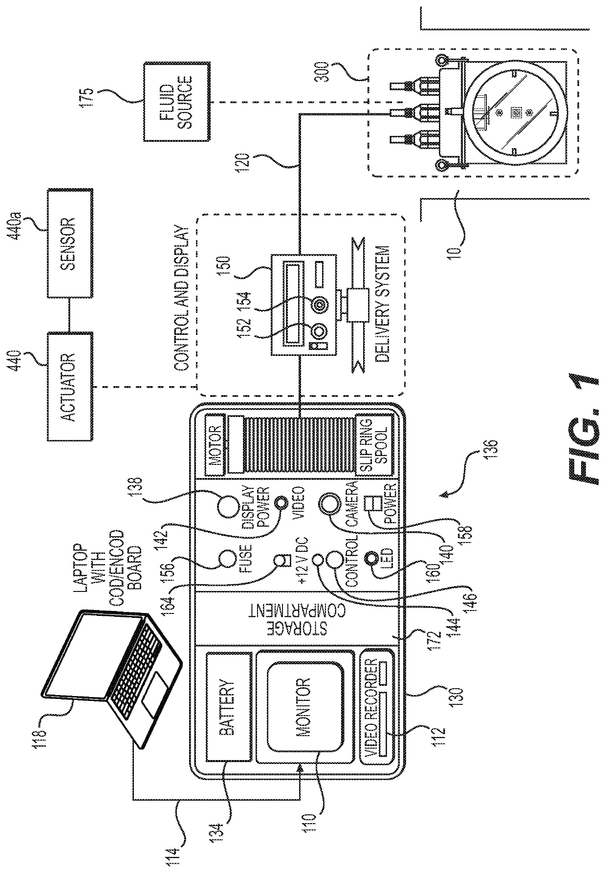
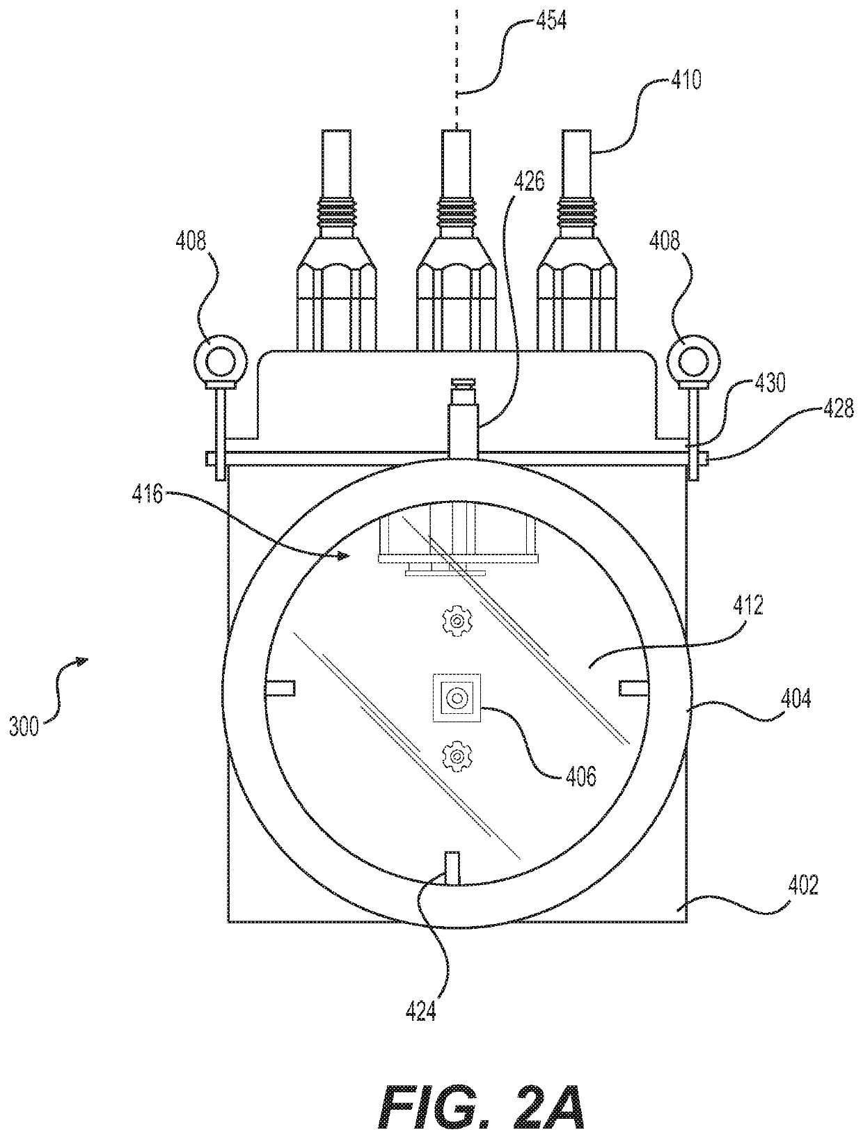
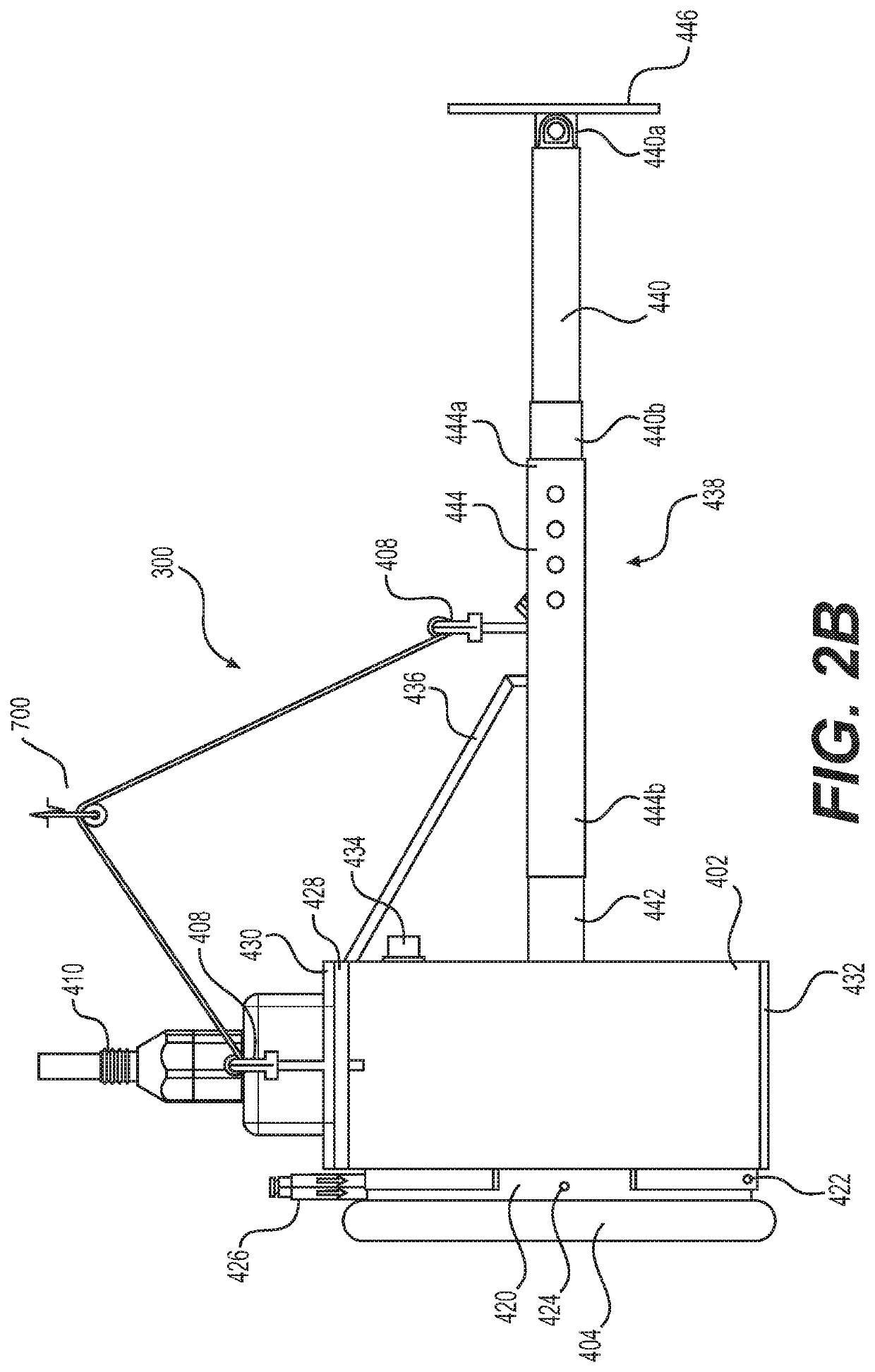
The patent is about a borescope, which is a device used for inspecting pipes and other piping systems. The borescope has a housing with a transparent window and a bumper surrounding the window. It also has an imaging assembly to visualize the field of view through the window. The borescope may also have a support assembly with telescoping rod sections and a linear actuator to adjust its length, and a controller to increase or stop the support assembly based on the current spike. The bumper is a circular tubing that presses against the surface to form a seal. The housing also has a support section with inlets and outlets for fluid, and a light source to illuminate the area being viewed. The imaging assembly is configured to rotate and pivot. Additionally, the borescope may have a plurality of strips that are movable relative to the housing and can be used to adjust the position of the borescope.

Problems solved by technology

However, such assumptions are not always warranted.
Unless project specifications and procedures are closely followed in the field, for example, the final shaft may have defects that can influence its structural and bearing capacity when filled.
Defects of a finished support structure and the conditions under which such defects occur may involve a number of causes.
For example, defects typically result from one or more of the following: 1) over-stressing the soil beneath the shaft base due to insufficient bearing (contact) area or because of unconsolidated materials located at the shaft base; 2) excessive mixing from mineral slurry, which can affect the development of concrete strength and / or formation of voids and cavities within the set concrete; and 3) structural discontinuities and / or deviations from the true vertical line causing local, undesirable stress concentrations.
In general, these and other defects can result in insufficient load transfer reducing the bearing capacity of the final structure and / or causing excessive settling during service.
Shaft failures have been attributed to insufficient borehole cleaning, and cleaning the base of boreholes often requires special tools.

Method used


Image

  • Borescope for drilled shaft inspection
  • Borescope for drilled shaft inspection
  • Borescope for drilled shaft inspection

Examples


Embodiment Construction

[0034]Reference will now be made in detail to aspects of the present disclosure, examples of which are illustrated in the accompanying drawings. Wherever possible, the same or similar reference numbers will be used through the drawings to refer to the same or like parts.

[0035]Both the foregoing general description and the following detailed description are exemplary and explanatory only and are not restrictive of the features, as claimed. As used herein, the terms “comprises,”“comprising,”“having,”“including,” or other variations thereof, are intended to cover a non-exclusive inclusion such that a process, method, article, or apparatus that comprises a list of elements does not include only those elements, but may include other elements not expressly listed or inherent to such a process, method, article, or apparatus. In this disclosure, relative terms, such as, for example, “about,”“substantially,”“generally,” and “approximately” are used to indicate a possible variation of ±10% in...


PUM

PropertyMeasurementUnit
diameteraaaaaaaaaa
diameteraaaaaaaaaa
diameteraaaaaaaaaa

Abstract

A borescope may include a housing including a transparent viewing window, a bumper surrounding at least a portion of a periphery of the transparent viewing window, wherein the bumper is configured to be pressurized by a fluid, and at least one imaging assembly configured to visualize a field of view exterior of the housing through the transparent viewing window.

Description

TECHNICAL FIELD[0001]The disclosure relates generally to a borescope system for use in inspecting and profiling drilled shafts, also referred to as bores or boreholes. In particular, the disclosure relates to a portable system for inspecting and profiling relatively large drilled construction shafts that may improve inspection efficiency in terms of maneuverability, information gathering, data recording, data analyzing, and data qualifying.INTRODUCTION[0002]Drilled construction shafts that are subsequently filled with concrete or similar materials provide support for many large building and infrastructure projects. For this reason, field engineers, and inspectors involved in preparing such shafts are particularly concerned with ensuring that the load transfers in side resistance and in end bearing are consistent with any assumptions made during the design phase.[0003]Normally, project design methods assume that drilled shafts are constructed under competent supervision with ample qu...

Claims


Application Information

Patent Timeline
Patent Type & Authority Patents(United States)
IPC IPC(8): G01N21/954E21B47/00E02D1/02H04N5/232H04N5/225
CPCH04N5/23241E02D1/02H04N5/2252E21B47/002H04N2005/2255G02B23/2476H04N23/555H04N23/66H04N23/695H04N23/51H04N23/65
Inventor AVASARALA, SWAMY KUMAR V.AVASARALA, PRANAVAVASARALA, PALLAVISUNKU, SOHAN KUMARRACHAKONDA, SAHITI
Owner AVER TECH INC
Learn More