
Method for monitoring compaction process in road construction and road roller

a technology of road construction and compaction process, which is applied in the direction of roads, roads maintainence, roads, etc., can solve the problems of large temperature difference between the laid asphalt layer and the inability to use complex and expensive systems, e.g., gps- or laser-based systems, etc., and achieves the effect of high monitoring resolution

Active Publication Date: 2020-06-09
BOMAG
View PDF22 Cites 0 Cited by
  • Summary
  • Abstract
  • Description
  • Claims
  • Application Information

AI Technical Summary

Benefits of technology

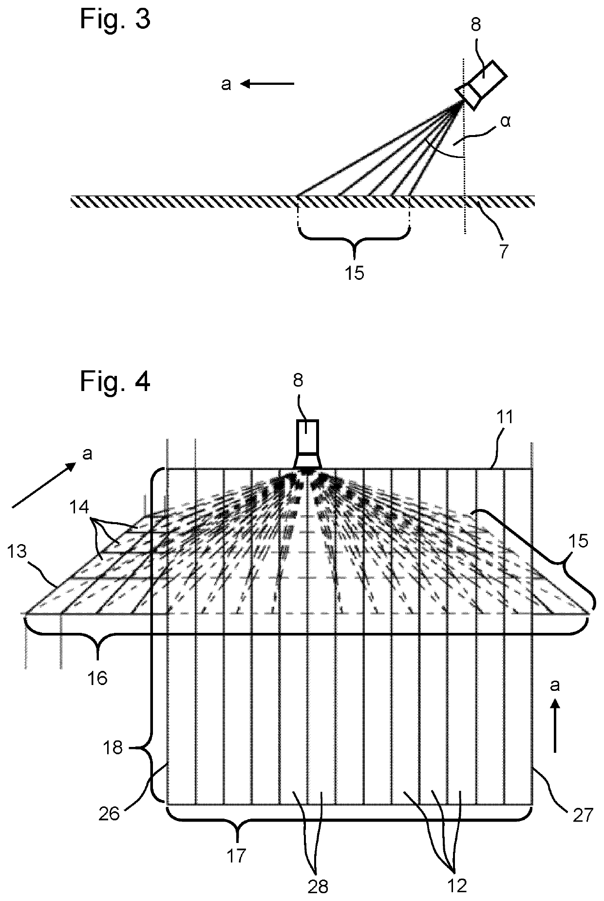
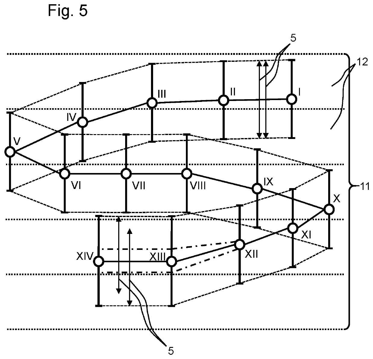
The present invention relates to a method for paving roads using a road roller and a temperature sensor. By using a single temperature sensor, the roller can be moved to determine the temperature across the road surface. The sensor can detect a temperature jump when the roller crosses an edge of the asphalt layer, indicating the position of the roller in relation to the asphalt strip. The detection of the edges can be repeated periodically, allowing the roller to determine its position in relation to each width segment of the asphalt path. The sensor can be a thermal imaging camera or infrared camera with resolution of several pixels. The width segments across the road surface are all equal in size or can be adjusted to provide higher monitoring resolution at the edges of the asphalt layer where there is a higher risk of insufficient compaction. The technical effect of the invention is to improve the monitoring and control of the road paving process for better quality roads.

Problems solved by technology

This always results in a large difference in temperature between the laid asphalt layer to be compacted and the ground adjacent to the asphalt layer, which is significantly colder than the asphalt.
In this manner, complex and expensive systems, e.g., GPS- or laser-based systems, are not necessary.

Method used


Image

  • Method for monitoring compaction process in road construction and road roller
  • Method for monitoring compaction process in road construction and road roller
  • Method for monitoring compaction process in road construction and road roller

Examples


Embodiment Construction

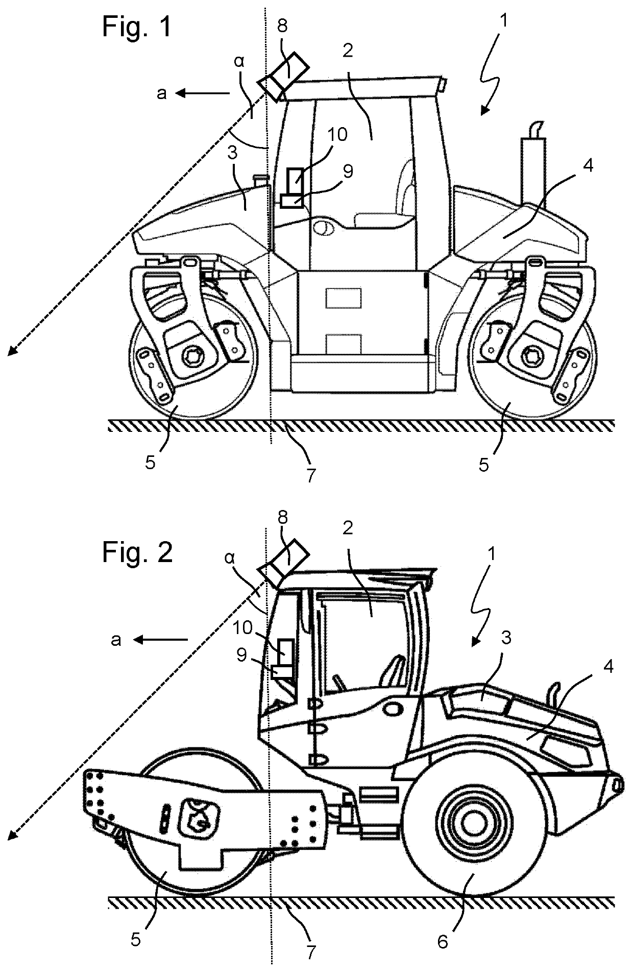
[0034]FIGS. 1 and 2 respectively show a road roller 1 with a driver's cab 2 and a machine frame 3. Moreover, the road rollers 1 have a drive engine 4, e.g., a diesel engine. FIG. 1 shows a tandem roller moving with its two roller drums 5 over the ground 7 to be compacted during a working operation. FIG. 2 shows a single-drum roller that has a roller drum 5 and additional wheels 6 with which the single-drum roller moves over the ground 7 to be compacted. During a working operation, the road rollers 1 frequently travel back and forth, so that they compact the ground 7 whether moving forward or backward. The forward movement is referred to as the working direction a, as indicated in the figures, even if the road rollers 1 can also work in the opposite direction, merely in order to illustrate the description.

[0035]The road rollers 1 comprise a temperature sensor 8 arranged at the essentially highest point of the road rollers 1. In the embodiment shown, this is the roof of the driver's c...


PUM


Abstract

A method for monitoring the compaction process of an asphalt layer to be compacted in road construction is provided comprising the steps: detecting the edges limiting the hot asphalt layer transversely to the road pathway by means of a temperature sensor arranged on a road roller compacting the asphalt layer, and dividing the detected asphalt layer into at least two width segments across the road pathway, wherein the position of the road roller on the asphalt layer transversely to the road pathway is determined from the measurement of the temperature sensor and is assigned to one of the width segments, the working operation of the road roller on the width segment is quantified via an operating parameter and stored, and the quantified working operation for each width segment is displayed to the operator for at least one past working interval. A road roller for carrying out the method is also provided.

Description

CROSS-REFERENCE TO RELATED APPLICATION[0001]The present application claims priority under 35 U.S.C. § 119 of German Patent Application No. 10 2017 008 602.8, filed Sep. 13, 2017, the disclosure of which is hereby incorporated herein by reference in its entirety.FIELD OF THE INVENTION[0002]The present invention relates to a method for monitoring the compaction process of an asphalt layer to be compacted in road construction. Moreover, the invention relates to a road roller, in particular a tandem roller, a single-drum roller or a rubber-tired roller, for carrying out the method.BACKGROUND OF THE INVENTION[0003]In road construction, hot asphalt is usually distributed transversely across the width of an intended road pathway before being smoothed and precompacted by a road paver, e.g., with a tamper beam and / or a paving screed. Further, while the asphalt material is still hot and plastic, the new road surface is usually further compacted by road rollers following the road paver, said r...

Claims


Application Information

Patent Timeline
Patent Type & Authority Patents(United States)
IPC IPC(8): E01C19/28E01C19/23E01C19/00
CPCE01C19/288E01C19/23E01C19/004
Inventor LAUGWITZ, NIELS
Owner BOMAG
Learn More