
Rotatable sole assembly

a technology of rotatable soles and soles, which is applied in the field of rotatable soles for shoes, can solve the problems of increasing the risk of occurrence of more severe injuries, affecting the comfort of wearing, etc., and achieves the effects of increasing torque, reducing the risk of injury, and reducing the stiffness of elastic materials

Active Publication Date: 2020-06-02
MUIRHEAD PETER DAVID
View PDF14 Cites 0 Cited by
  • Summary
  • Abstract
  • Description
  • Claims
  • Application Information

AI Technical Summary

Benefits of technology

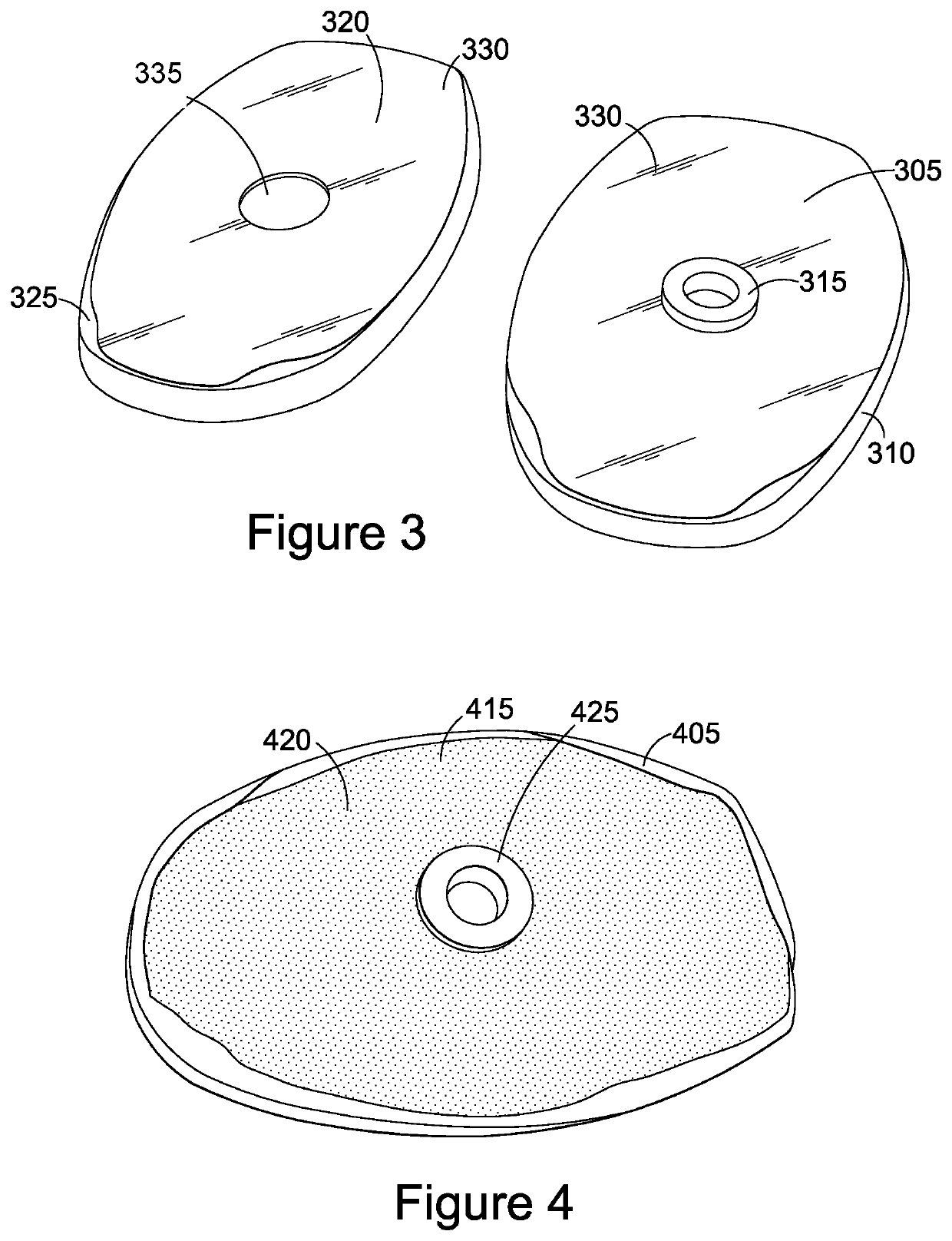
[0018]It would be appreciated that the term “coating layer” covers both a discrete layer provided between the first and second plates (e.g. graphite powder) and a layer formed or produced from the first and second plates (e.g. when the nylon material or molybdenum sulphide material is used as the plates). It is intended that a slippery effect is provided and / or produced between the plates by means of the coating layer.
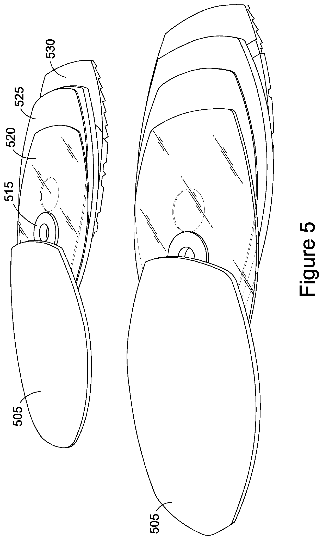
[0019]Whilst the prior art shoes mainly use metal (mechanical) joints and / or pivots to facilitate the rotation of the sole, the sole assembly above does not need any metal joints and / or pivots. It simply uses plates, for example, plastic plates which are attached to the respective sole slabs. There is a coating layer formed between the plates, which ensures that each part of the sole assembly is rotatable with respect to one another. Furthermore, the sole assembly may also include an elastic material holding the both parts of the sole assembly. The elastic modulus (stiffness / elasticity) of this material controls the rotation of the sole assembly. This material ensures that the assembly returns to the original position after the rotation. Since there are no metal joints, bearings or pivots being used in the sole assembly, it is very easy and cost effective to manufacture. Further, it has significantly less weight compared to the prior art soles. It also reduces the risk of any injury if the metal joints / mechanism were to come through the body of the shoe. The proposed sole assembly is designed to reduce the overall torque experienced in the knee of an athlete or service personnel, or to assist the aged, infirm or disabled with general mobility, and to ultimately avoid high levels that could cause or exacerbate injury. The invention is also designed to reduce Anterior Cruciate Ligament (ACL) injuries.
[0020]Furthermore, it would be appreciated that the invention relates to a midsole which is attached between the front part of a shoe body and an outer front sole of the shoe. Thus the midsole does not have to be manufactured at the same time of manufacturing a shoe. It can be manufactured as a separate mechanism and then can be installed to any existing / host shoes. It can be removed from the shoe as necessary and thus the proposed design provides better flexibility to a shoe wearer and / or a shoe manufacturer. The proposed sole assembly can be fitted to any types of shoes, for example, a golf shoe, a cricket shoe, a football shoe, a tennis shoe, a basketball shoe and / or a rugby shoe. The sole assembly should not be only restricted to a sports shoe. It can be equally used in other type shoes as well. For example, it can be used in regular consumer shoes. It can also be used in other applications, e.g. outdoor, personal-protective-equipment (PPE), hiking and military applications.
[0040]The sole assembly may be configured to reduce a torque applied to the front end portion of the body portion of the shoe.

Problems solved by technology

This can cause significant stress to muscles, ligaments and tendons which can cause injuries over time.
Properly fitting sports shoes do not allow the foot to substantially move within the shoe.
This is essential to prevent minor injuries such as blisters which can negatively affect performance but can increase the risk of occurrence of more severe injuries due to increased traction related to spikes becoming embedded in the ground.
For many people, complete rest is not possible as they may need to work or they may have children to look after.
It is often just not convenient to rest for long periods of time in order to recover from injury.
Therefore, it is not uncommon for lower limb injuries to cause recurring pain and suffering due to more damage being caused by simply carrying on with normal life.
Such mechanical metal components add a significant amount of weight to the shoe.
These components can also be dangerous in a situation if they were to come through from the sole to the main body of the shoe.
This reduces flexibility and increases manufacturing costs.
The mechanical metal rotation mechanism also does not adequately reduce torque through the front end portion of the shoe.
Furthermore, since the grommet is attached using an adhesive material, it may not operate exactly the same way as a metal / mechanical grommet.

Method used


Image

  • Rotatable sole assembly
  • Rotatable sole assembly
  • Rotatable sole assembly

Examples


Embodiment Construction

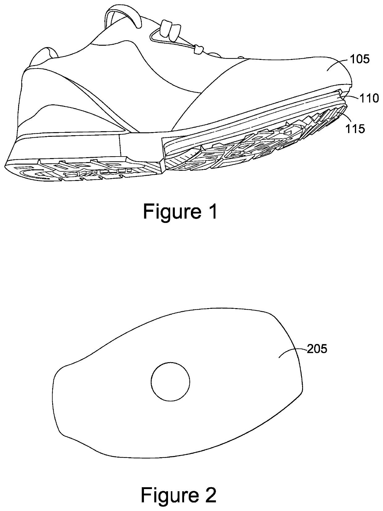
[0082]The rotation (tare) “Torc” mechanism is a midsole component or midsole assembly that can be incorporated into many types of footwear at the time of manufacture. It allows for rotation of the foot relative to the floor whilst still maintaining frictional contact, and buffering the transfer of potentially painful or damaging torque forces to the lower leg of the wearer.

[0083]Installation of the mechanism does not alter the weight or feel of the footwear, and adds nothing to the thickness of the host shoe. Generally, the rotation mechanism (or the midsole assembly) is adhered in place on the forepart of the host shoe, with the original outsole (which is sliced off the midsole when it was removed from the host shoe) stuck to the bottom of the mechanism to maintain its slip resistance properties. It allows the wearer to rotate the forepart of their shoe relative to the ground without either compromising slip resistance or transferring potentially damaging torque forces through the ...


PUM


Abstract

We disclose herein a rotatable sole assembly for a shoe which comprises a first plate (305), a second plate (320); and a coating layer (330) between the first and second plates. The coating layer (330) is configured to rotate one of the first and second plates with respect to the other of the first and second plates. The sole assembly is designed to reduce ACL injuries as well as the incidence of other lower leg injuries related to high torque forces.

Description

FIELD OF THE INVENTION[0001]This invention relates to a rotatable sole for a shoe, particularly but not exclusively, to a rotatable midsole attachable to a shoe.BACKGROUND TO THE INVENTION[0002]Many sports, such as soccer, rugby, basketball, baseball and tennis, amongst others, require the athlete to frequently change direction. This can cause significant stress to muscles, ligaments and tendons which can cause injuries over time. It is not uncommon for athletes to also suffer more traumatic injuries as a result of twisting an ankle beyond its normal range of movement.[0003]A number of sports, such as soccer, golf, rugby, sprinting and cross country, amongst others, utilise footwear having spikes, studs or other means of improving traction. Properly fitting sports shoes do not allow the foot to substantially move within the shoe. This is essential to prevent minor injuries such as blisters which can negatively affect performance but can increase the risk of occurrence of more severe...

Claims


Application Information

Patent Timeline
Patent Type & Authority Patents(United States)
IPC IPC(8): A43B13/14A43B3/00
CPCA43B13/14A43B3/0042A43B5/00A43B13/00
Inventor SMITH, DAVID ROGERBAYES, THOMAS JOHN WILLIAMMUIRHEAD, PHILIP DAVID
Owner MUIRHEAD PETER DAVID
Learn More