
Pusher arm and ball release mechanism for embolic coils

a pusher arm and coil technology, applied in the field of medical devices and medical procedures, can solve the problems of difficult repositioning or retrieval of coils if desired, inability to control the positioning of coils at the site to a fine degree of accuracy, and undesirable limitations of the technique of plunging coils from the distal end of the catheter, so as to reduce the risk of occlusion, and reduce the effect of occlusion

Active Publication Date: 2020-04-28
BOSTON SCI SCIMED INC
View PDF8 Cites 3 Cited by
  • Summary
  • Abstract
  • Description
  • Claims
  • Application Information

AI Technical Summary

Benefits of technology

Enables precise placement and reliable detachment of embolic coils with improved mechanical efficiency, reducing the need for multiple coils and maintaining catheter flexibility while ensuring 100% detachment reliability without increased size or expense.

Problems solved by technology

This technique of plunging the coil from the distal end of the catheter has undesirable limitations.
First, because of the plunging action of the pusher during deployment, the positioning of the coil at the site cannot be controlled to a fine degree of accuracy.
Second, once plunged from the catheter, it is difficult to reposition or retrieve the coil if desired.
While current detachment mechanisms are generally reliable, they may not release the coil when triggered 100% of the time.
In the case of mechanical detachment mechanisms in particular, improving detachment reliability may involve undesirable trade-offs such as increasing the size and / or cost of parts used in detachment mechanisms.

Method used


Image

  • Pusher arm and ball release mechanism for embolic coils
  • Pusher arm and ball release mechanism for embolic coils
  • Pusher arm and ball release mechanism for embolic coils

Examples


Embodiment Construction

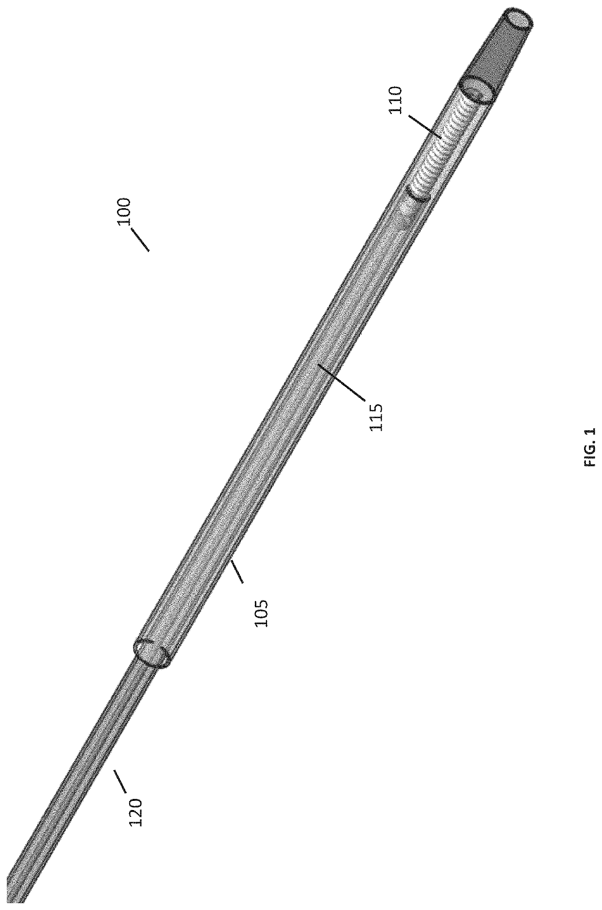
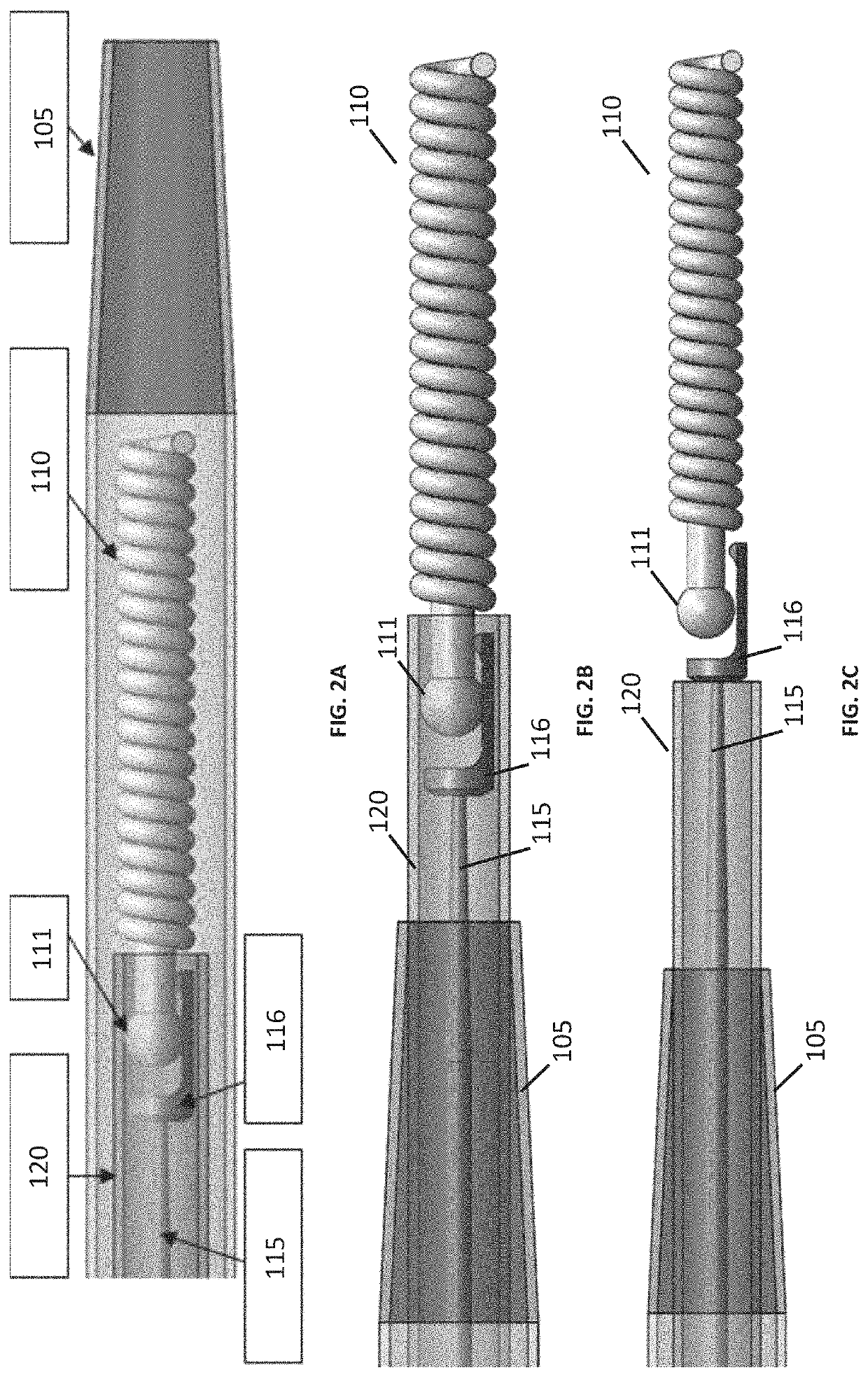
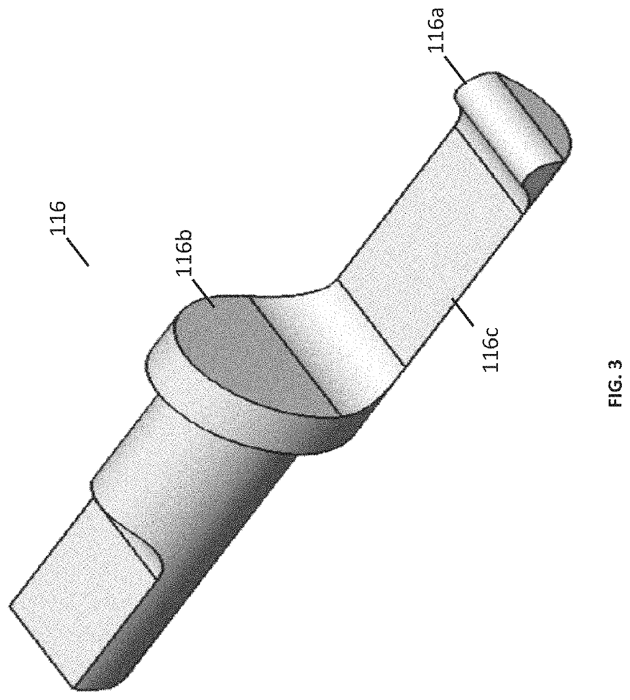
[0016]An exemplary catheter assembly 100, as shown in FIG. 1, includes a generally tubular catheter 105, an embolic coil 110 (though any other implantable medical device of similar size may be used) having, at its proximal end, a ball or other bulbous element 111, a pusher assembly 115 slidably disposed within the catheter 105 and having, at its distal end, a receiving element 116 that is sized to engage the ball 111. The catheter assembly 100 also includes a constraining element 120 that is slidable within the catheter lumen independently of the pusher assembly 115 and which constrains the axial or radial movement of the ball 111 when it is engaged with the receiving element 116.

[0017]The constraining element 120 depicted in FIGS. 1 and 2 has a generally tubular distal end and has an inner diameter that is slightly larger than the combined width of the ball111 and the receiving element 115 when the two are engaged (e.g. 10% larger, 20% larger, 30% larger, 40% larger or 50% larger)....


PUM


Abstract

This disclosure concerns release mechanisms for medical implants, particularly embolic coils and the like, which utilize bulbous elements and receiving elements to constrain the bulbous elements. In some cases, the receiving elements are sized and shaped to help constrain the bulbous element axially and / or radially, and may work in concert with constraining elements and / or release wires that are optionally moveable independently of the receiving elements.

Description

PRIORITY[0001]This application claims the benefit of priority under 35 U.S.C. § 119 to U.S. Provisional Patent Application Ser. No. 62 / 237,904, filed Oct. 6, 2015, which is incorporated by reference in its entirety and for all purposes.FIELD OF THE INVENTION[0002]This application relates to the field of medical devices and medical procedures. More particularly, the application is related to devices and methods for occluding body lumens such as blood vessels.BACKGROUND[0003]Therapeutic embolization or occlusion of blood vessels may be used to treat a variety of vascular and non-vascular conditions including cerebral and peripheral aneurysms, arteriovenous malformation, uterine fibroids and various tumors. One commonly used agent for embolizing blood vessels is the embolic coil, a permanently implanted coiled wire structure which, when implanted into a blood vessel, occludes the vessel by causing thrombosis where it is deployed. Embolic coils may have different lengths and / or cross-se...

Claims


Application Information

Patent Timeline
Patent Type & Authority Patents(United States)
IPC IPC(8): A61B17/12
CPCA61B17/12145A61B17/1214A61B17/12031A61B2017/12054
Inventor TASSONI, NICHOLASANDERSON, MARY-CLAIREPEDERSON, GARYZHANG, KENWILLARD, MARTIN R
Owner BOSTON SCI SCIMED INC
Learn More