
Method for manufacturing bicycle crank

a manufacturing method and crank technology, applied in the field of bicycle crank manufacturing, can solve the problems of easy cracking and damage, weak connection between the crank and the crank shaft, and inconvenient assembly of the crank, so as to improve the structural strength of the bicycle crank, and reduce the weight of the bicycle crank

Active Publication Date: 2020-04-21
ALEX GLOBAL TECH
View PDF5 Cites 0 Cited by
  • Summary
  • Abstract
  • Description
  • Claims
  • Application Information

AI Technical Summary

Benefits of technology

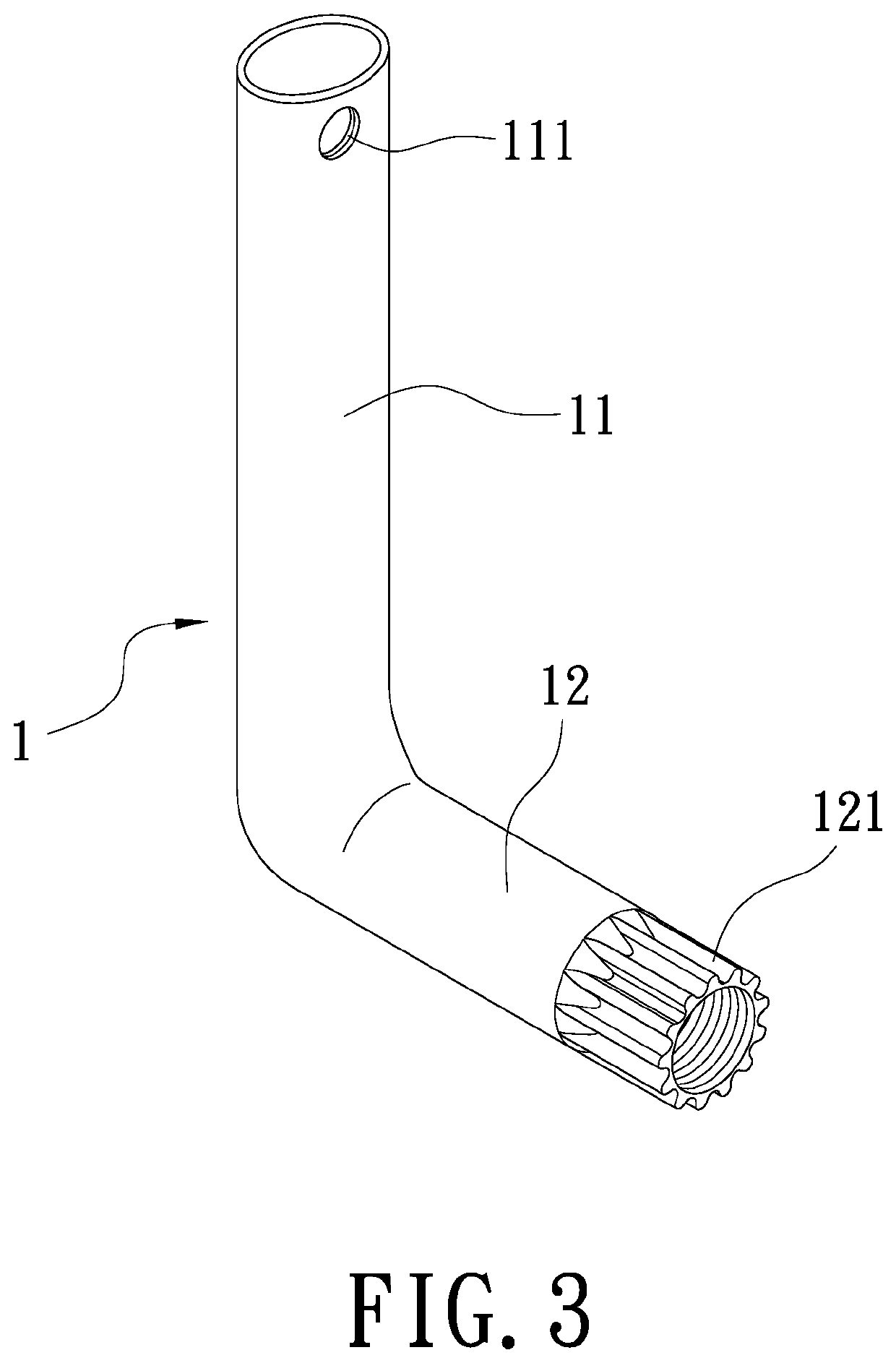
[0006]Therefore it is a primary object of the present invention to provide a method for manufacturing a bicycle crank by which an integrated bicycle crank is produced. Not only the assembly of the bicycle crank is easier and more convenient, the structural strength of the bicycle crank is increased effectively because that the bicycle crank is integrally formed, without being connected by threads. Thereby the bicycle crank is more durable to large and frequent impacts. The weight of the bicycle crank is reduced so that the bicycle is lightweight. The bicycle crank is more streamlined and beautiful so as to attract consumers and increase the market competitiveness.

Problems solved by technology

The assembly of the crank, the crankshaft and the pedal is not convenient.
The structural strength of the connection between the crank and the crankshaft is weaker so that cracking and damage occurs easily.
The increased weight of the assembly has negative effects on the whole weight of the bicycle.

Method used


Image

  • Method for manufacturing bicycle crank
  • Method for manufacturing bicycle crank
  • Method for manufacturing bicycle crank

Examples


Embodiment Construction

[0014]In order to learn technical content, functions and features of the present invention more clearly, please refer to the following detailed descriptions, related figures and reference numbers therein.

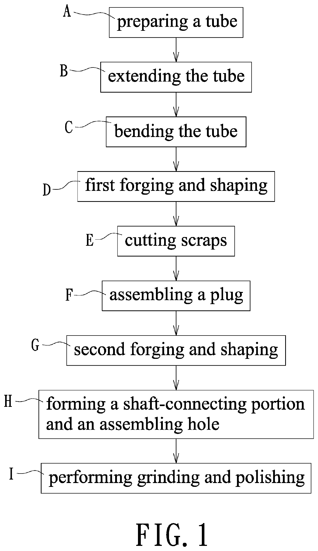
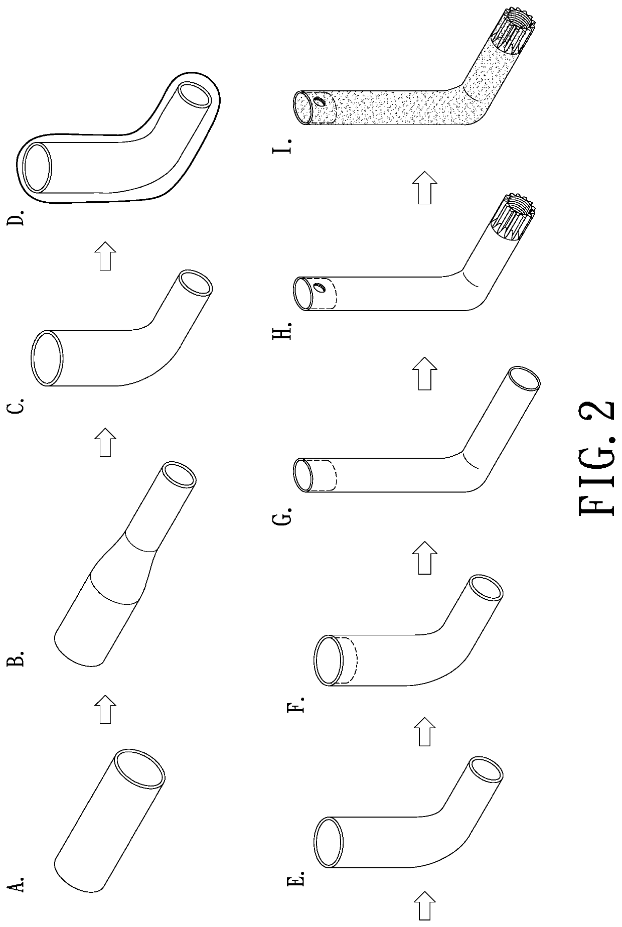
[0015]Refer to FIG. 1 and FIG. 2, a method for manufacturing a bicycle crank according to the present invention includes the following steps.

[0016](A) preparing a tube: preparing aluminum alloy pipe with a certain length;

[0017](B) extending the tube: extending one end of the tube to the length required so that one end of the tube becomes a narrower crankshaft portion while the other end thereof forms a crank portion.

[0018](C) bending the tube; bending the crankshaft portion of the tube so that the crankshaft portion and the crank portion are integrally connected to form an L-shaped part;

[0019](D) first forging and shaping: placing the L-shaped tube into a mold cavity of a first mold so that the tube is forged into the shape of the mold cavity of the first mold. At this step, the cra...


PUM

PropertyMeasurementUnit
lengthaaaaaaaaaa
shapeaaaaaaaaaa
structural strengthaaaaaaaaaa

Abstract

A method for manufacturing a bicycle crank is revealed. After being extended, bent and forged, an aluminum alloy pipe becomes an L-shaped part formed by a cylindrical crankshaft portion and an oval crank portion integrally connected to each other. A plug is inserted into an outer end of the crank portion while a periphery of an outer end of the crankshaft portion is punched to form a shaft-connecting portion. An assembling hole is arranged at the outer end of the crank portion, corresponding to the plug. Thus a bicycle crank is produced. Thereby not only the assembly of the bicycle crank is easier and more convenient, the structural strength of the bicycle crank is increased effectively to against vibrations and impacts. The bicycle is lightweight and the bicycle crank is more streamlined so that consumers are attracted. Thereby the market competitiveness is increased.

Description

BACKGROUND OF THE INVENTIONField of the Invention[0001]The present invention relates to a method for manufacturing a bicycle crank, especially to a method for manufacturing a bicycle crank by which not only the assembly of the bicycle crank is easier and more convenient, the structural strength of the bicycle crank is improved significantly. Thus the bicycle crank is more durable to large and frequent vibrations. The weight of the bicycle crank is reduced so that the bicycle is lightweight. The bicycle crank is more streamlined and beautiful so as to attract consumers and increase the market competitiveness.Description of Related Art[0002]Instead of walk, bicycles are a great transportation option. The vehicle is moved along with user's feet steering the wheels. Riding bicycles is not only for fitness but also as a recreation. No fuel is required to run the bicycle so that the bicycle is energy efficient and environment friendly. For students that are too young to ride motorcycles o...

Claims


Application Information

Patent Timeline
Patent Type & Authority Patents(United States)
IPC IPC(8): B62M3/00B21D7/00B21D53/86B23P15/00B21K17/00B21J5/00
CPCB21D53/86B21K17/00B62M3/00B21J5/002B23P15/00B21D7/00B21K1/08
Inventor CHEN, WEI-CHIN
Owner ALEX GLOBAL TECH
Learn More