
Sheath for bra wire ring and method for manufacturing bras using the same

a technology of wire ring and bra, which is applied in the field of bra, can solve the problems of affecting beauty, affecting comfort, and too tight sheath, and achieve the effect of enhancing the comfort of wearing the bra for females

Active Publication Date: 2020-04-21
KAIPING KELIAN KNITTERS DEV
View PDF4 Cites 0 Cited by
  • Summary
  • Abstract
  • Description
  • Claims
  • Application Information

AI Technical Summary

Benefits of technology

The invention provides a sheath for bra wire rings that can improve the resistance while inserting the wire rings. The sheath has a hollow part for holding the wire ring and a core wire that can slide relative to the sheath, which prevents the sheath from being flattened during the sewing process. After pulling out the core wire, a hollow part can be formed in the middle of the sheath for convenient wire rings to pass through. The support from the core wire helps maintain the fluffiness of the bra and improves wearing comfort. The width and thickness of the core wire are greater than those of the wire ring to ensure enough gap for inserting the wire ring and easy insertion of the core wire into the hollow sheath body. Overall, this bra wire ring sheath solves the problem of resistance and prevents issues like wrinkles, holes, and tightness, resulting in a more beautiful and comfortable bra for females.

Problems solved by technology

Furthermore, after the wire ring is inserted into the sheath, it will result in that the sheath is too tight to be fluffy.
The formation of wrinkles or holes and the tightness of the sheath will not only affect the beauty of bra, also even affect the comfort of wearing the bra for females.

Method used


Image

  • Sheath for bra wire ring and method for manufacturing bras using the same
  • Sheath for bra wire ring and method for manufacturing bras using the same
  • Sheath for bra wire ring and method for manufacturing bras using the same

Examples


Embodiment Construction

[0017]The invention will be further explained by combining with the specific embodiments below. Wherein, the attached drawings are only used for exemplary description, representing the schematic diagrams only, rather than pictures of real product, and it is not to be understood that the invention is limited to the drawings and embodiments.

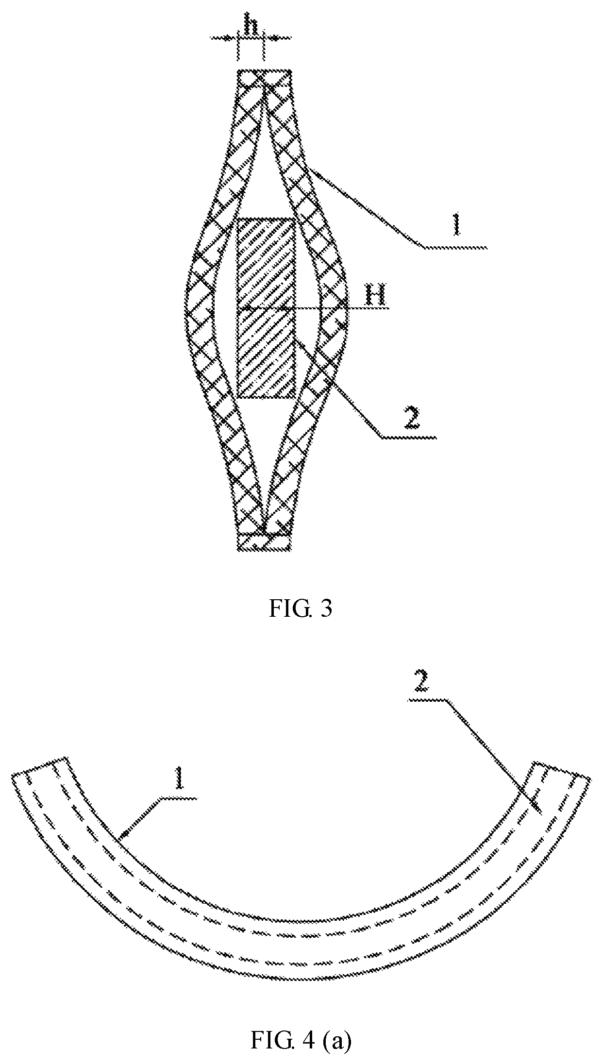
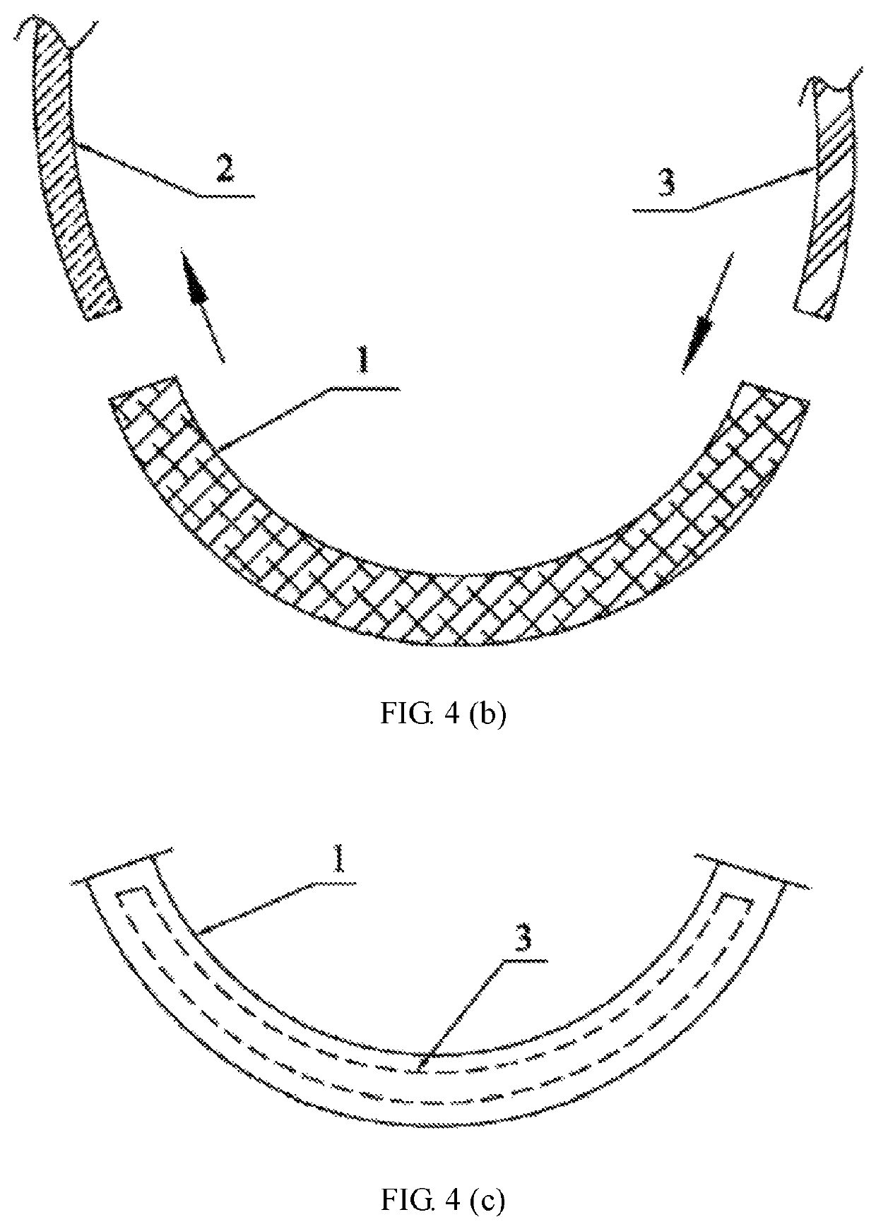
[0018]As shown in FIGS. 1-3, a sheath for bra wire ring according to the invention comprises a hollow sheath body made of cloth, in which a hollow part for holding the wire ring to be installed is provided and also comprises a core wire penetrated through the hollow part, which may slide relative to the hollow sheath body. The core wire 2 is independent relative to the hollow sheath body 1 and can be pulled out from the hollow sheath body 1 as required. The length of the core wire 2 is not shorter than that of the hollow sheath body 1, and more preferably the length of the core wire is equal to that of the hollow sheath body. The width d and thickn...


PUM

PropertyMeasurementUnit
lengthaaaaaaaaaa
widthaaaaaaaaaa
thicknessaaaaaaaaaa

Abstract

The invention discloses a sheath for bra wire ring. It includes a hollow sheath body made of cloth, and there is a hollow part for holding the wire ring to be inserted in the hollow sheath body; it also comprises a core wire inserted in the hollow part, and the core wire slides relative to the hollow sheath body. Such design solves the problem of resistance when the wire rings are inserted into a flat bra wire ring sheath, resulting in that in the process of manufacturing bra, the phenomena of wrinkles and holes left on the surface of the sheath and the tightness of the sheath caused by inserting wire rings can be obviously improved, and making the product more beautiful and simultaneously enhancing the comfort of wearing the bra for females.

Description

TECHNICAL FIELD[0001]The invention relates to the technical field of bra, in particular to a sheath for bra wire ring and a method for manufacturing bras by using the sheath.BACKGROUND[0002]A bra plays an indispensable role to females' appearance shaping and health, and the wire ring under the bra cup has an effect of supporting and protecting the breasts. Since the wire ring can't be sewn together with other parts of the bra because of its material, a sheath for bra wire ring has been designed in the industry, so that the wire ring is combined with other parts of the bra through sewing the sheath for bra wire ring with the other parts of the bra into an integration and inserting the wire into the sheath. As a result, the manufacturing process and time of placing wire rings in the bra are reduced, and the discomfort to the skin caused by the stiff material of the wire rings is buffered, which eliminates the tension to the skin caused by the wire rings to a certain extent.[0003]Altho...

Claims


Application Information

Patent Timeline
Patent Type & Authority Patents(United States)
IPC IPC(8): A41C3/12A41C3/00
CPCA41C3/0007A41C3/122A41C3/0021A41C3/12
Inventor CHEUNG, SUILUNG
Owner KAIPING KELIAN KNITTERS DEV
Learn More