
Sill component for the sill of a vehicle body

a vehicle body and component technology, applied in the direction of vehicle components, superstructure connections, superstructure subunits, etc., can solve the problems of dissipation of pole energy, relative deformation and disadvantages of known sill components in stability, so as to improve stability and a defined plastic deformation behavior in a crash situation, and facilitate the configuration of necessary force-transmitting connections. , the effect of simple and inexpensive manner

Active Publication Date: 2020-04-14
DR ING H C F PORSCHE AG
View PDF11 Cites 2 Cited by
  • Summary
  • Abstract
  • Description
  • Claims
  • Application Information

AI Technical Summary

Benefits of technology

The invention provides a reinforcing component in a receiving space that helps distribute and stabilize forces caused by a side pole crash. This helps to reduce deformation of the outer shell and ensures a greater use of the inner profile. The invention also reduces complexity in the manufacture of the receiving space and allows for a more defined plastic deformation behavior in a crash situation. The reinforcing component helps cushion the force absorbed by the outer shell and dissipates it up and / or down into the connecting sections and complementary connecting sections, resulting in less plastic deformation in the longitudinal direction. The invention also allows for a smaller deformation space in the interior of the vehicle body. Overall, the invention results in improved mechanical stability and performance of the sill component in a pole crash.

Problems solved by technology

Known sill components often have disadvantages with regard to the stability in the case of a particular form of crash that is known as the side pole crash.
Thus, the side pole crash causes a relatively pronounced deformation of the known sill component toward the interior compartment of the vehicle body.
More particularly, the deformation of the sill component into the clearance dissipates the energy of the pole.
However, this clearance is no longer made available as useful space.
The necessary clearance for the sill of the sill component reduces the maximum possible useful size or the maximum possible useful space for the associated battery apparatus.

Method used


Image

  • Sill component for the sill of a vehicle body
  • Sill component for the sill of a vehicle body
  • Sill component for the sill of a vehicle body

Examples


Embodiment Construction

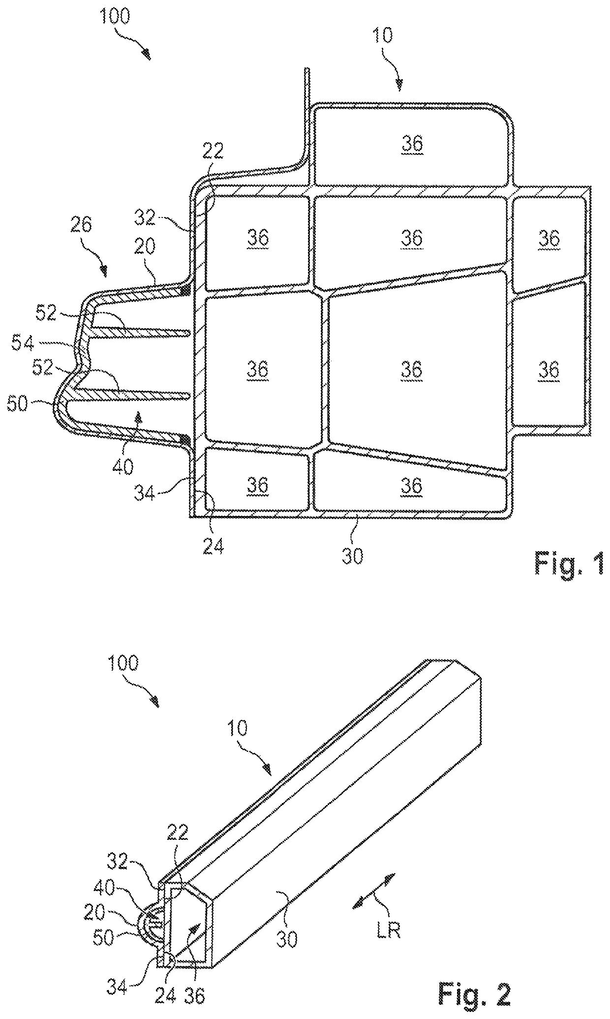
[0036]FIG. 1 diagrammatically shows a cross section through a sill component 10 of a vehicle body 100 according to one embodiment of the invention. The longitudinal direction LR is perpendicular to the plane of the drawing of FIG. 1.

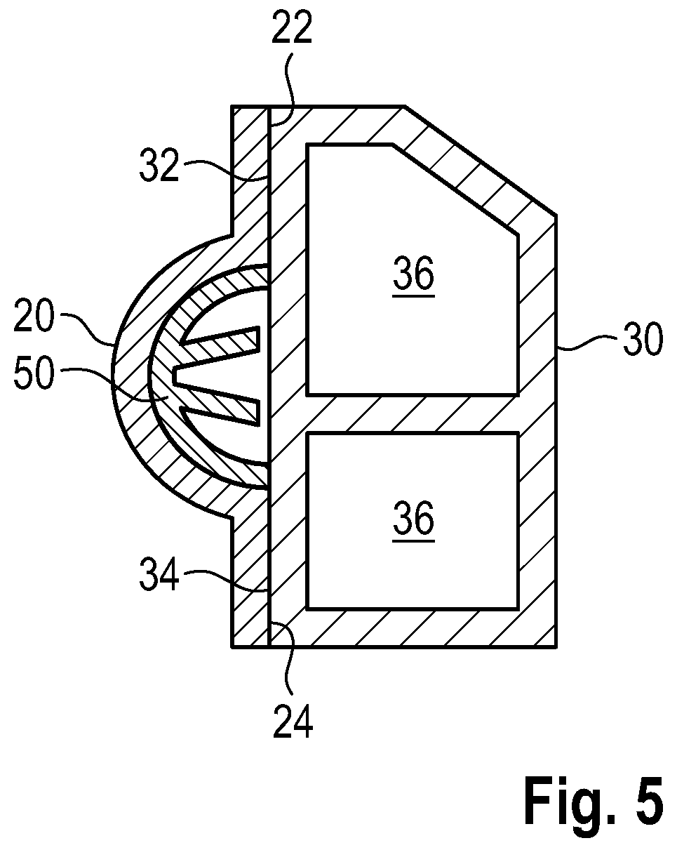
[0037]As can be seen clearly in FIG. 1, the sill component 10 is equipped with three fundamental components, namely, an outer shell 20, an inner profile 30, and a reinforcing component 50. The outer shell 20 is a metal plate and closes the sill component 10 toward the outside. A pole crash exerts an action of force on the outer shell 20 locally and a deformation of the outer shell 20 will follow. The introduced force is supported in the outer shell 20 by way of the reinforcing component 50 that is situated here in a protuberance 26 in a receiving space 40. More particularly, the protuberance 26 forms a convex outer surface and a concave inner surface facing toward the receiving space 40 and toward the inner profile 30. A reinforcing component 50 with two...


PUM


Abstract

A sill component (10) for the sill of a vehicle body (100) has an outer shell (20) made from a metal material and an inner profile (30) made from an aluminum material. The outer shell (20) is connected via a first connection section (22) to a first complementary connecting section (32) of the inner profile (30) and via at least one second connecting section (24) to at least one second complementary connecting section (34) of the inner profile (30) in a manner that transmits force along a longitudinal direction (LR) of the vehicle body (100). At least one receiving space (40) is arranged between the two connecting sections (22, 24) and a reinforcing component (50) is in the receiving space (40) for the mechanical reinforcement of the outer shell (20).

Description

CROSS REFERENCE TO RELATED APPLICATION[0001]This application claims priority under 35 USC 119 to German Patent Appl. No. 10 2017 124 391.7 filed on Oct. 19, 2017, the entire disclosure of which is incorporated herein by reference.BACKGROUNDField of the Invention[0002]The invention relates to a sill component for the sill of a vehicle body, and to a method for producing a sill component of this type.Related Art[0003]A vehicle body should be designed to absorb mechanical loads during the operation of the vehicle and to ensure mechanical protection for the vehicle and the passenger compartment. The vehicle body includes sill components that are attached on the left and right sides of the vehicle in the region of the undertray. Sill components usually delimit the vehicle body on the left and right sides between the front and rear wheel arches. Known sill components usually are manufactured from a homogeneous material, for example from metal shells. The use of aluminum profiles is also g...

Claims


Application Information

Patent Timeline
Patent Type & Authority Patents(United States)
IPC IPC(8): B62D25/02B62D29/00B62D21/15B62D27/02
CPCB62D25/025B62D27/023B62D29/008B62D29/005B62D21/157
Inventor KELLNER, PHILIPPBOHLIEN, JENS
Owner DR ING H C F PORSCHE AG
Learn More