Bar member, assembled component and robot
a technology of assembled components and components, applied in the direction of gearing, mechanical control devices, instruments, etc., can solve the problems of large burden on units and personnel in all walks of life, low applicability and performance-cost ratio, and uneven quality of existing robot products, and achieve strong expansion functions, enlarge the universality of a component, and rich configurations
- Summary
- Abstract
- Description
- Claims
- Application Information
AI Technical Summary
Benefits of technology
Problems solved by technology
Method used
Image

Examples
embodiment 1
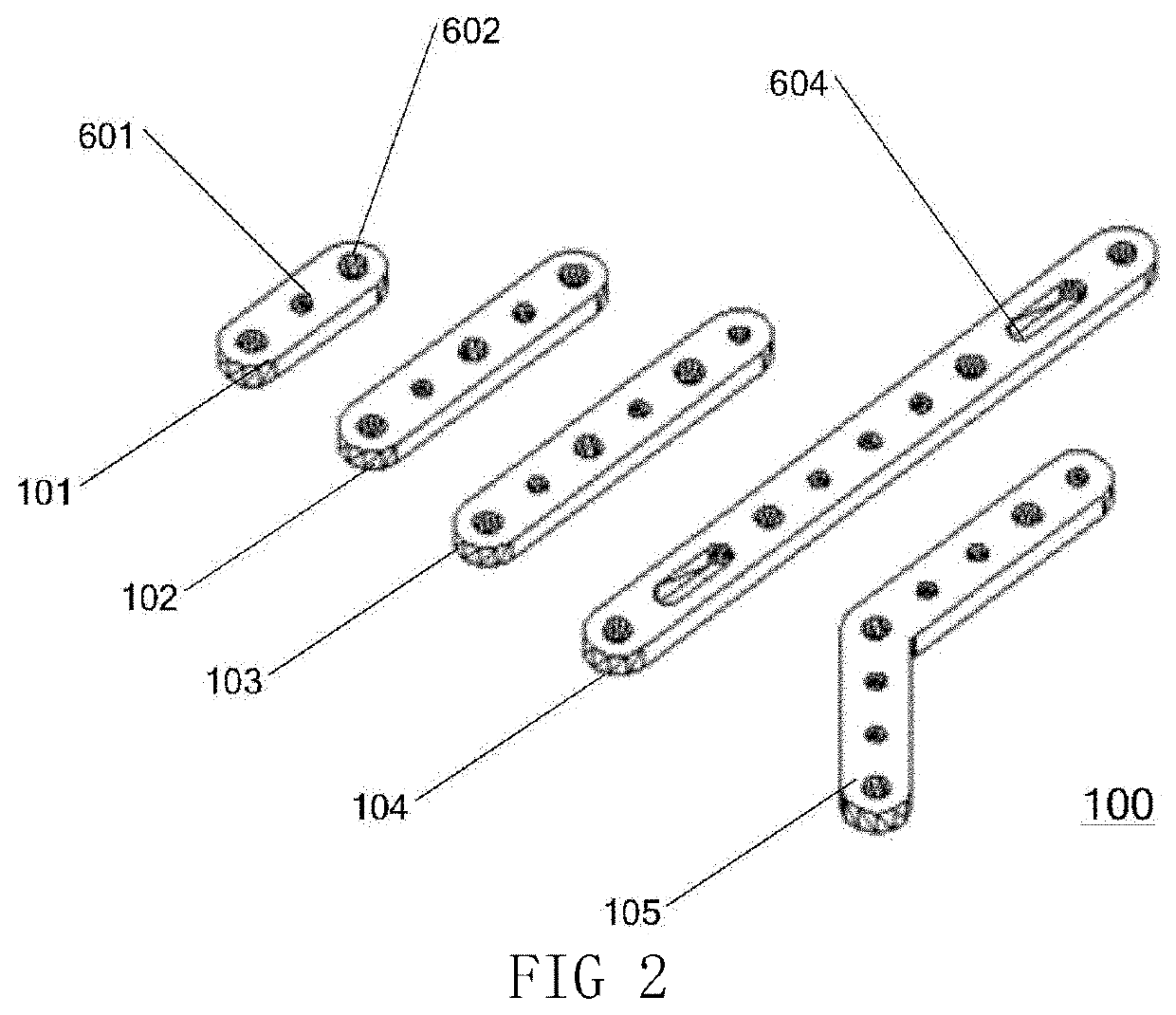
[0086]As shown in FIGS. 11-18, a bar member is provided, where the bar member has a width and a thickness. The width of the bar member is four times of the thickness thereof. Connecting holes running through the bar member along a thickness direction of the bar member are provided on the bar member. For example, the width of the bar member may be 9.8 mm to 10 mm. The thickness may be 2.4 mm to 2.5 mm.
[0087]Through trial and error, the inventor has found that, when the ratio of the width to thickness of the bar member is 4:1, the need of conveniently realizing the most variety of movement mechanisms may be satisfied. The most variety of movement functions may be achieved.
[0088]Specifically, the connecting holes include connecting holes A 602 and connecting holes B 601. The aperture of each of the connecting holes A 602 is greater than that of the connecting holes B 601. For example, the connecting holes A 602 may each have a diameter of 4 mm to 4.2 mm. The connecting holes B 601 may ...
embodiment 2
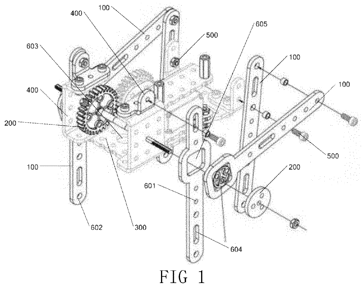
[0098]FIG. 19 is a structural diagram of a driving mechanism assembled by using an assembled component.
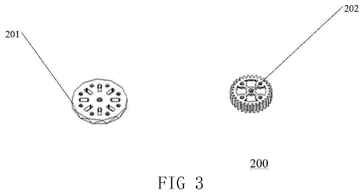
[0099]An assembled component includes a moving member and a fixed member. The moving member includes at least one of a multi-hole bar member and a multi-hole circular plate. The multi-hole bar member is the bar member in the embodiments described above. The multi-hole circular plate has a central hole and a plurality of fixed holes that are distributed around the central hole and arranged circumferentially. The fixed member includes a multi-hole plate and a multi-hole bent plate. The thickness of the multi-hole plate is the same as that of the multi-hole bar member. A plurality of fixed holes are arranged in a matrix provided on the multi-hole plate. A bent portion is formed by bending at least one end of the multi-hole bent plate. A plurality of fixed holes are distributed on the multi-hole bent plate in a matrix.
[0100]By using the above-described bar member to form an assembled c...
embodiment 3
[0104]A robot is provided with the assembled component.
[0105]FIG. 20 is a structural diagram of a crawler-type walking robot in Embodiment 3. In the robot, a single-sided triangle frame is formed by a bar member. A platform for containing an article to be transported is formed by a multi-hole plate member. A bent member and a mounting platform of a driving motor are formed on the top by using a bent member.
[0106]By using the above-described bar member to form an assembled component and matching with a fixed member having the same thickness, the size is even. Moreover, it is convenient to construct robots, teaching aids or movement mechanisms in various forms to research or verify the feasibility of movement mechanisms. By enlarging models assembled by the assembled component in scale to different degrees, specific movement mechanisms may be formed. When these movement mechanisms are applied in production practices, it is advantageous to shorten the development cycle and quicken the ...
PUM
 Abstract
Description
Claims
Application Information
 - R&D
- Intellectual Property
- Life Sciences
- Materials
- Tech Scout
- Unparalleled Data Quality
- Higher Quality Content
- 60% Fewer Hallucinations
Browse by: Latest US Patents, China's latest patents, Technical Efficacy Thesaurus, Application Domain, Technology Topic, Popular Technical Reports.
© 2025 PatSnap. All rights reserved.Legal|Privacy policy|Modern Slavery Act Transparency Statement|Sitemap|About US| Contact US: help@patsnap.com