
Light emitting device combining light from several LEDs

a technology of led collimators and light emitting devices, which is applied in the direction of lighting and heating apparatus, instruments, condensers, etc., can solve the problems of limited number of led collimators that will fit, high light loss, and bulky led spots, etc., and achieves the effect of small and compact structure, easy production, and reduced production costs

Active Publication Date: 2020-03-10
SIGNIFY HLDG BV
View PDF16 Cites 0 Cited by
  • Summary
  • Abstract
  • Description
  • Claims
  • Application Information

AI Technical Summary

Benefits of technology

[0008]It is an object of the present invention to overcome this problem, and to provide a light emitting device with which a minimum of light is lost as the light from several different LED light sources is combined, which is smaller and more compact in structure and which is cheaper and easier to produce.

Problems solved by technology

Such LED spots, however, are bulky because each source requires an individual collimator.
Since the area of the exit surface of the spot is limited, only a limited number of LED collimators will fit.
This solution, however, is disadvantageous due to the thermal restrictions arising from the heat generation of the LED sources.
The use of an optical manifold, however, leads to very high losses of light as the light is guided from the input surfaces to the output surface of the optical manifold.
This solution, however, still exhibits high losses of light from the optical manifold.
Furthermore, this solution still requires an individual collimator for each LED source, and therefore does not solve the above problems related to bulkiness.
Furthermore, the requirement for an individual collimator for each LED source also leads to high production costs.

Method used


Image

  • Light emitting device combining light from several LEDs
  • Light emitting device combining light from several LEDs
  • Light emitting device combining light from several LEDs

Examples


example

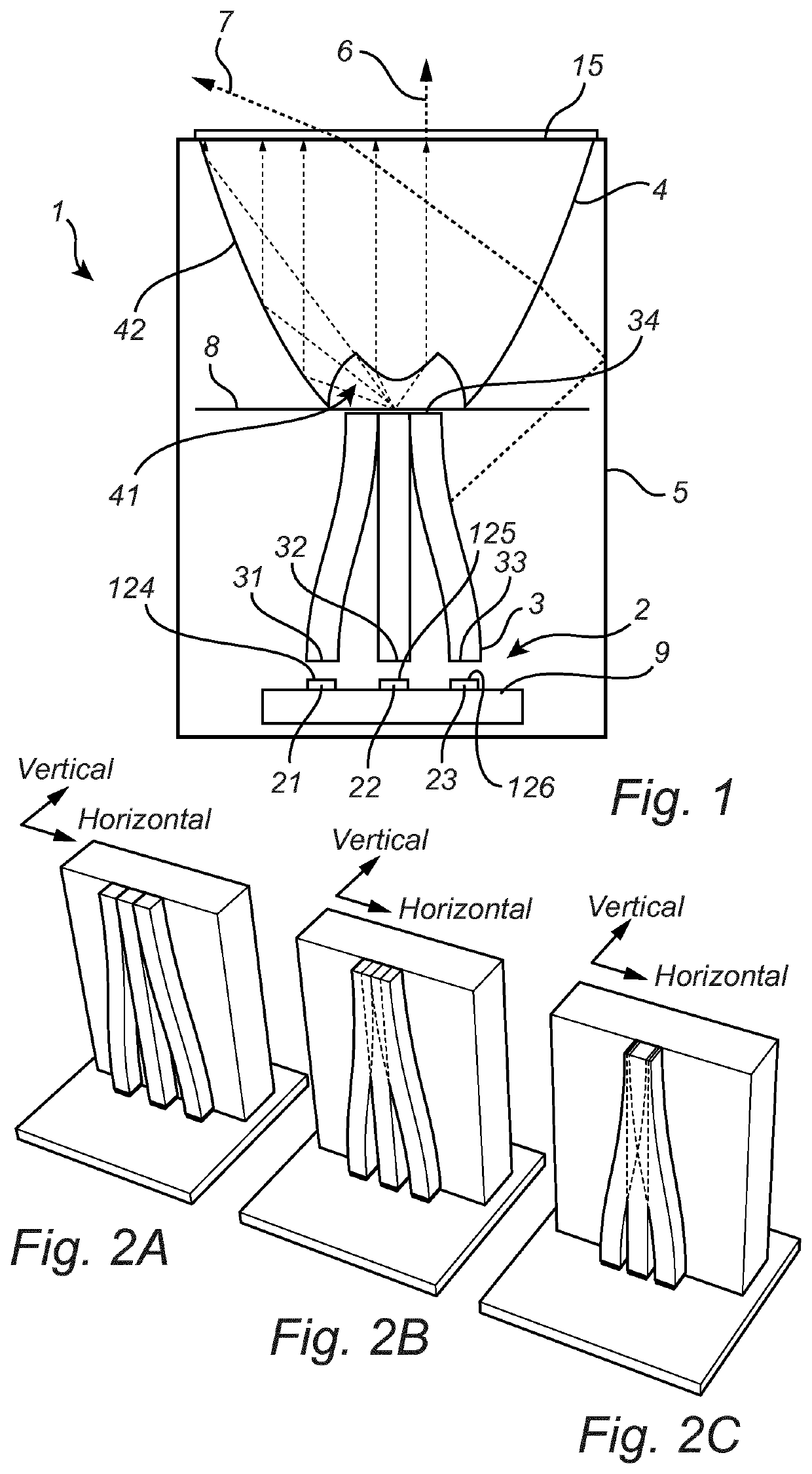
[0066]Turning now to FIGS. 2A, 2B and 2C, as a way of a non-limiting example, three different optical manifolds are shown each combining the light of three LEDs. The light guide output surface 34 of the optical manifold is chosen to be equal (FIG. 2A), ⅔ (FIG. 2B) and ½ (FIG. 2C) of the sum of the light guide input surfaces 31, 32, 33, respectively.

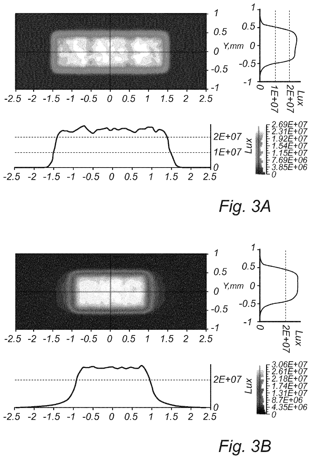
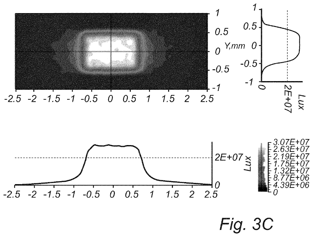
[0067]FIGS. 3A, 3B and 3C show the illuminance distribution at the light guide output surface of each of the light guiding elements of the light emitting devices shown in FIGS. 2A, 2B and 2C, respectively. From the optical ray trace analysis, the results of which are shown in FIGS. 3A, 3B and 3C, respectively, it may be seen that the luminous flux through the light guide output surface 34 decreases, in this particular example from 75 lm (FIG. 3A) to 58 lm (FIG. 3B) to 44 lm (FIG. 3C), but the flux per area increases by about 20% from 25 lm / mm2 to about 30 lm / mm2. This is a surprising and unexpected result, since the flux per area is commo...


PUM

PropertyMeasurementUnit
refractive indexaaaaaaaaaa
lengthsaaaaaaaaaa

Abstract

A light emitting device (1, 101) comprising a plurality of LEDs (2), each LED (21, 22, 23) of said plurality of LEDs comprising a LED output surface (24, 25, 26) and being arranged to, in operation, emit light from said LED output surface, a light guiding element (3) comprising a light guide input surface (31) being arranged adjacent said LED output surface of each LED of said plurality of LEDs such that said light emitted by said plurality of LEDs is injected into the light guiding element at said light guide input surface, said light guiding element further comprising a light guide output surface (34), said light being injected into the light guiding element at said light guide input surface further being guided to and emitted from said light guide output surface, and a collimating element (4) made of a transparent material and comprising a first surface section (41) arranged adjacent said light guide output surface and said collimating element being adapted to collimate light emitted from said light guide output surface and injected into said collimating element at said first surface section, the light emitting device further comprising a first reflective element (5) arranged such as to enclose at least said light guiding element at least partially and wherein said collimating element comprises a second surface section (42), wherein the first reflective element is adapted to inject at least a part of light reflected back by the first reflective element into said collimating element at said second surface section.

Description

CROSS-REFERENCE TO PRIOR APPLICATIONS[0001]This application is the U.S. National Phase application under 35 U.S.C. § 371 of International Application No. PCT / EP2016 / 061894, filed on May 26, 2016, which claims the benefit of European Patent Application No. 15169874.3, filed on May 29, 2015. These applications are hereby incorporated by reference herein.FIELD OF THE INVENTION[0002]The invention concerns a light emitting device comprising a plurality of LEDs, each LED of the plurality of LEDs comprising a LED output surface and being arranged to, in operation, emit light from the LED output surface, and a light guiding element comprising a light guide input surface being arranged adjacent the LED output surface of each LED of the plurality of LEDs such that the light emitted by the plurality of LEDs is injected into the light guiding element at the light guide input surface, the light guiding element further comprising a light guide output surface, the light being injected into the lig...

Claims


Application Information

Patent Timeline
Patent Type & Authority Patents(United States)
IPC IPC(8): F21K9/61F21K9/62F21K9/69F21V8/00F21Y115/10
CPCF21K9/61F21K9/69F21K9/62G02B6/0006G02B6/0008F21Y2115/10F21V7/0091F21V7/22F21V2200/40F21K9/20F21K9/68F21K9/00G02B19/0028G02B19/0066G02B27/1006G02B27/143G02B27/149
Inventor CORNELISSEN, HUGO JOHANMOS, BARRY
Owner SIGNIFY HLDG BV
Learn More