Trailer restraint with auxiliary securing/locking mechanism

a technology trailer restraint, which is applied in the direction of transportation and packaging, loading/unloading, etc., can solve the problems of retraction of auxiliary locking mechanism, inadvertent and unsafe departure of trailer from loading bay, etc., to prevent excessive “dock-walking”, improve the working environment of the dock, and improve the grip of the rig bar

Active Publication Date: 2020-02-25
NORDOCK
View PDF25 Cites 5 Cited by
  • Summary
  • Abstract
  • Description
  • Claims
  • Application Information

AI Technical Summary

Benefits of technology

An advantage of the present impact trailer restraint is that the hook remains engaged to the RIG bar during use. The trailer restraint includes an auxiliary locking mechanism that prevents the hook from rotating out of engagement with the RIG bar during the loading and unloading process. The hook and auxiliary locking mechanism combine so that an inadvertent departure by a driver or the up and down, back and forth trailer movements (“dock-walk”) during the loading and unloading process do not cause inadvertent disengagement of the restraint from the RIG bar.
Another advantage of the impact trailer restraint is its versatility. The trailer restraint not only captures a wide variety of RIG bars by wrapping around the top front corner of the RIG bar to better grip the RIG bar, it also captures RIG bars with obstructions preventing the hook from wrapping around its top front corner. The hook combines with the auxiliary locking mechanism to engage and capture the RIG bar and its obstruction. During an inadvertent pull-out by a driver or should the hook begin to “walk down” the obstructed RIG bar, the auxiliary locking mechanism engages the lower front corner of the RIG bar or its obstruction to stop the downward progression of the hook. The hook remains engaged with the RIG bar to prevent the hook from “walking-off” the RIG bar, the RIG bar from “walking-off” the trailer restraint, and an inadvertent and unsafe departure of the trailer from the loading bay.
A further advantage of the present trailer restraint is its power and reliability. The restraint overcomes the power of a truck should the driver inadvertently attempt to pull the trailer away from the dock, even when a RIG bar obstruction prevents the hook from gripping the top surface of the RIG bar. The restraint and its combined hook and auxiliary locking mechanisms are designed to withstand 100,000 pounds of trailer pull away force. The present trailer restraint not only prevents excessive “dock-walk”from disengaging the hook from the RIG bar, it also prevent inadvertent trail pull-away when the hook is still engaging the RIG bar or an obstruction. Thus, the restraint reliably improves the dock working environment posed by these safety risks.
A further advantage of the present trailer restraint is its user friendly nature. In most loading and unloading situations, the auxiliary locking mechanism is not needed. The driver does not attempt to drive away from the dock when the hook is engaged, and a RIG bar obstruction does not result in excessive “dock walk.” In these situations, the RIG bar or an obstruction do not engage the auxiliary locking mechanism. When the auxiliary locking mechanism is not engaged, the trailer does not need to be backed up to release the locking mechanism. The hook and locking mechanisms can be lowered to their retracted positions without the need of the extra backing up step by the truck driver, which improves the overall efficiency in using the trailer restraint while ensuring dock safety.
A still further advantage of the present impact trailer restraint is the passive design of the auxiliary locking mechanism. The auxiliary locking mechanism does not require an independent motor or drive system. A spring biasing mechanism is used to deploy the auxiliary locking mechanism. The movement of the hook allows for the activation and deactivation of the biasing mechanism to keep the hook and auxiliary locking mechanism engaged with the RIG during use.
A still further advantage of the present impact vehicle restraint is its rugged durability in harsh working environments. The non-complex nature and movements of the hook and auxiliary locking mechanism reduce manufacturing costs, binding, jamming, wear and tear and maintenance costs, which improves the overall reliability and working life of the device.

Problems solved by technology

The retraction of the hook by the motor overpowers the biasing mechanism and causes the retraction of the auxiliary locking mechanism.
The hook remains engaged with the RIG bar to prevent the hook from “walking-off” the RIG bar, the RIG bar from “walking-off” the trailer restraint, and an inadvertent and unsafe departure of the trailer from the loading bay.

Method used


Image

  • Trailer restraint with auxiliary securing/locking mechanism
  • Trailer restraint with auxiliary securing/locking mechanism
  • Trailer restraint with auxiliary securing/locking mechanism

Examples


Embodiment Construction

While this invention is susceptible of embodiments in many different forms, the drawings show and the specification describes a preferred embodiment of the invention. It should be understood that the drawings and specification are to be considered an exemplification of the principles of the invention. They are not intended to limit the broad aspects of the invention to the embodiment illustrated.

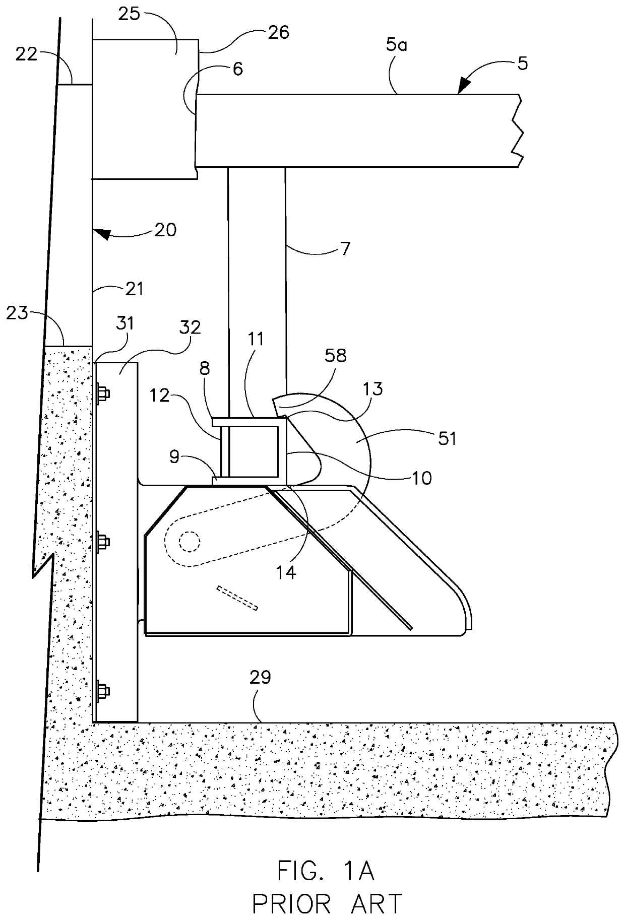
Conventional truck trailers 5 have a rear end 6 equipped with a mounting structure 7 for a rear impact guard (RIG) or ICC bar 8. The RIG mounting structure 7 extends down from a location proximal to and generally a few inches from the trailer rear end 6. The RIG bar or beam 8 is generally an elongated horizontal bar. The bar 8 is generally parallel to and spans the width of the rear end 6 of trailer 5, and is used to facilitate loading and unloading the vehicle. The bar 8 has a generally square or rectangular cross-sectional shape with four sides 9-12 as shown in FIG. 1A. The bar 8 has a low...


PUM


Abstract

The present invention is an impact vehicle restraint with a hook and auxiliary securing / locking mechanism that combine to secure the RIG bar of a trailer to a loading dock. A motor rotates the hook between retracted and extended positions. When extended, the hook secures and holds the RIG bar to the dock. When the hook is extended, the auxiliary securing / locking mechanism is also extended to and held at a set position by a biasing mechanism. When the hook is blocked by an obstruction, forward movement of the trailer causes the RIG bar and the obstruction to slide into engagement with the auxiliary securing / locking mechanism, which accepts the RIG bar and obstruction and moves to a locked position to secure the RIG bar. The retraction of the hook by the motor overpowers the biasing mechanism and causes the retraction of the auxiliary securing / locking mechanism.

Description

FIELD OF THE INVENTIONThe invention pertains to an impact vehicle restraint with a hook and auxiliary locking mechanism to engage and hold a trailer to a loading dock during the loading and unloading of the trailer.BACKGROUND OF THE INVENTIONVehicle restraints are utilized to increase safety at a loading dock. The restraints secure a truck trailer to the loading dock structure or building when goods are transferred between the trailer and the building. The restraints typically engage a rear horizontal bar referred to as the rear impact guard (RIG) or ICC bar. The RIG or ICC bar is located at the rear end of the trailer below the trailer bed. When the trailer is backed up to an available loading dock stall, the RIG bar is positioned close to the face wall of the dock. Bumpers typically extend from the face wall to protect the trailer, dock and any dock leveling fixture at the dock. Trailer restraints typically include a hooking device located in front of the dock and anchored to the ...

Claims


Application Information

Patent Timeline
Patent Type & Authority Patents(United States)
IPC IPC(8): B65G69/00
CPCB65G69/003
Inventor GLEASON, DENIS
Owner NORDOCK
Why Eureka
Try Eureka