
Method of torque control and apparatus thereof

a technology of torque control and torque, applied in the direction of process and machine control, manufacturing tools, instruments, etc., can solve the problems of unstable working air pressure, large deviation of output torque, and difficult control of output torque magnitude, etc., to achieve accurate tightening torque, economic, reliable, and effective

Active Publication Date: 2020-02-18
CHINA PNEUMATIC CORP
View PDF18 Cites 4 Cited by
  • Summary
  • Abstract
  • Description
  • Claims
  • Application Information

AI Technical Summary

Benefits of technology

[0020]Throughout the operation of the torque tool, the microprocessor may promptly notify the operator through a display device or a warning device, based on the pressure variation feedback from the air pressure sensor, and whether the air pressure is within the permissible range upon the completion of the fastening process. In this way, the tool is able to perform the fastening operation under stable working air pressure, and the output torque thereof can be controlled accurately.
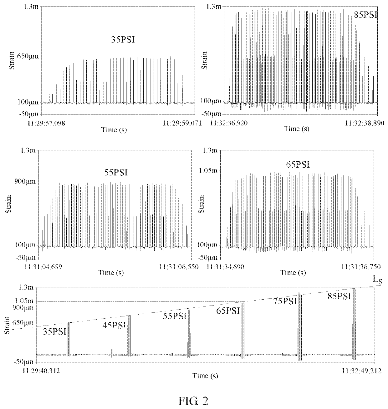
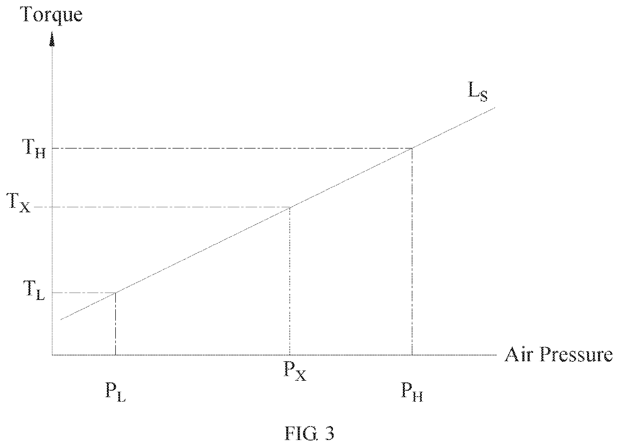
[0022]Taking advantage of the characteristics of the impact or oil pulse torque tool, which is “under a predetermined operating conditions, e.g. same airflow rate and same fastening duration, and under a stable working air pressure that is to be monitored throughout the operation, the same tool will produce the same stable torque”, the method of controlling torque and the torque control apparatus of the present invention perform calibration using torque measuring device before the fastening operation, and a “correspondence curve between the air pressure and the torque values for the tool under known operating conditions that are predetermined” is constructed. Furthermore, after the fastening operation, verify again whether the tightening torque is within the predetermined range; the aforementioned torque correction may be performed whenever necessary, such that a fastening operation with a more accurate tightening torque may be achieved; therefore, the torque tool no longer require the precision of its torque control apparatus or various sensors to control its output torque; instead, with the method of controlling torque and the torque control apparatus of the present invention, the fastening operation of the impact or pulse torque wrench can be controlled in a more economic, reliable, and effective manner compared to any control technique known in the art.

Problems solved by technology

For all the torque tools driven by compressed air, such as pneumatic impact wrenches, pneumatic oil pulse wrenches, pneumatic torque multipliers, pneumatic screwdrivers with clutch, and so on, their test results or operating performance tend to be affected by an unstable working air pressure during the process of testing or operating them.
Since the compressed air driving the pneumatic torque tools is affected by the factors such as the capability of the on-site compressed air system to supply gas, the torque driving structure of the tools, and the air consumptions of the tools, it is hard to control the magnitudes of their output torques.
However, since the working air pressure during the fastening operation is not stable, the airflow to the tool is directly affected, which in turn causes the deviation of the output torque to be extremely large.
Even if the tool is disposed with a torque measuring device, the frequency and amplitude of the vibration that arises from the impact will pose difficulty for the analysis of signals, and hence it will be difficult to control the torque output effectively.
Despite having a better torque control precision compared to the former, numerous factors, such as the unstable air pressure during the fastening process directly affecting the airflow to the tool, or the structural feature of the hydraulic cylinder and the rising temperature of the hydraulic fluid inside the cylinder during continuous operation, tend to limit the range of adjustment and the control precision of the torque.
The precision thereof is higher albeit the time it takes to fasten is longer, and the slow speed results in low efficiency, not to mention the tool is heavier, which tends to cause fatigue in the operator.
A torque tool with clutch is a tool that achieves torque control via a pneumatic motor working in conjunction with the planetary reduction gearing, in addition to the tension of a spring pushing against the clutch; while it has an acceptable control precision, nevertheless, when the operation of the tool is halted, the reaction force generated increases as the torque output of the tool increases, thereby making it difficult to handle the tool for a prolonged period of time, or even causing issues such as fatigue or occupational injury such as elbow arthritis to the operation personnel.
Their results, however, are quite limited.
However, since the pulse signals generated by the impacts of the impact or oil pulse torque tools are erratic and the fastening duration thereof is too short, it is hard to control the torque of such tools.
In addition, when the detected signals, which are generated by those electronic detection apparatus installed in the tools, is to be transmitted to the built-in or external control apparatus of the tool, so as to shut off the air supply in real-time, the accuracy of the torque control is bound to be affected because of the hysteresis of the signal transmission when the signals are being relayed between electronic and the mechanical components, such as between the microprocessor and the solenoid valve; moreover, the conditions of the fastener and the object to be fastened, e.g. the material, surface smoothness, hardness or surface lubrication, or even the way the operator holding the tool while fastening, will directly or indirectly affect the accuracy of the torque control.

Method used


Image

  • Method of torque control and apparatus thereof
  • Method of torque control and apparatus thereof
  • Method of torque control and apparatus thereof

Examples


Embodiment Construction

[0030]Various aspects such as the technical features, advantages or content of the present disclosure will be set forth in detail in the form of preferred embodiments hereinafter, and the description will be made along with reference to the attached drawings, which are solely illustrative and serve to provide better understanding of the present disclosure only, the scale and / or proportion of any portion of the drawing do not represent the actual configuration of the disclosure, hence the scale, proportion or shape in the drawings should not be misconstrued as limiting the scope of the disclosure.

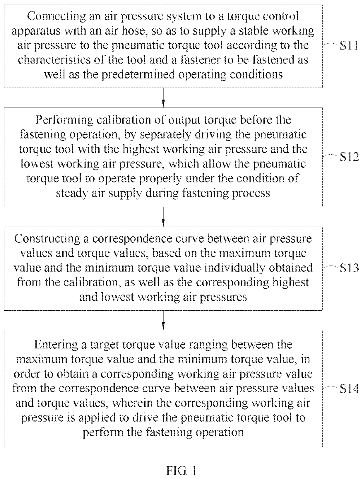
[0031]Please refer to FIG. 1, which is a flowchart illustrating the steps according to the method of controlling torque of the present invention. As shown in the drawing, method of controlling torque of the present invention may include the following steps: (S11) connecting an air pressure system to a torque control apparatus with an air hose, so as to supply a stable working air pressure to...


PUM


Abstract

A method of torque control and a torque control apparatus for a pneumatic torque tool are provided. The method includes: connecting a torque control apparatus between an air supply system and a pneumatic torque tool; under predetermined working and control conditions, driving the pneumatic torque tool at the first and second working air pressures to calibrate output torque, and to obtain maximum and minimum torque values; constructing correspondence curve between air pressure and torque value based on the first and second working air pressures and the maximum and minimum torque values obtained; entering any target torque value ranging from minimum torque value to maximum torque value of the correspondence curve to obtain a corresponding working air pressure value and drive the pneumatic torque tool; and verifying whether all working and control conditions are controlled within a predetermined range of variation to control the output torque.

Description

BACKGROUND OF THE INVENTION[0001]1. Field of the Invention[0002]The present invention relates to a method of controlling torque and an apparatus using the same, and more particularly, a method of controlling torque and an apparatus using the same, which control the output torque under the predetermined working and control conditions, according to a correspondence between the air pressure and the torque constructed in advance.[0003]2. Description of the Related Art[0004]For all the torque tools driven by compressed air, such as pneumatic impact wrenches, pneumatic oil pulse wrenches, pneumatic torque multipliers, pneumatic screwdrivers with clutch, and so on, their test results or operating performance tend to be affected by an unstable working air pressure during the process of testing or operating them. Conventional pneumatic torque tools usually have their torque controlled by the pressure or airflow of the compressed air driving those tools. Since the compressed air driving the p...

Claims


Application Information

Patent Timeline
Patent Type & Authority Patents(United States)
IPC IPC(8): G05D17/02B23P19/06B25B23/145
CPCG05D17/02B25B23/1453B23P19/066B25B23/1456B23P19/06
Inventor CHU, HSIU-FENG
Owner CHINA PNEUMATIC CORP
Learn More