
Replacement Window Cladding Method and System

a technology for replacing windows and cladding, applied in the direction of window/door frames, wing arrangements, sills/thresholds, etc., can solve the problems of reducing the amount of vision glass by as much as five inches, creating a double frame, and occupying a substantial amount of space, so as to maintain the integrity of the home or structure, the effect of widening the trim and extending the sill

Active Publication Date: 2020-02-11
PIGOTT AGENCY LLC
View PDF11 Cites 3 Cited by
  • Summary
  • Abstract
  • Description
  • Claims
  • Application Information

AI Technical Summary

Benefits of technology

This window replacement method and system solves problems that have existed since the 1960s. The method uses the secure portion of the frame where connected to the interior of the structure, without disrupting the interior lead paint. The new construction window technology matches the warmth and beauty of the home without loss of egress or view glass. The window replacement unit can be certified to "Energy Star" standards. The installation requires complete inspection of the home. Exterior insulating finish systems or stucco can also use this system as it deals with the exterior. The system provides proper and better window replacement without leaks, loss of glass size, or loss of egress for fire department and building owners. The interior of the existing frame is not disturbed. Standard new construction window accessories fit into the accessory kerf to allow wider trims and larger sills made from low maintenance materials.

Problems solved by technology

A drawback of window replacement using a window unit having its own frame is that it creates a double frame, which takes up a substantial amount of space in the old frame and reduces the amount of vision glass by as much as five inches.
Another drawback of current methods is that they do not allow for installation of insulation between the window frame and the stud opening gap or pocket.
A further drawback of current methods is that the overall appearance of the original window is changed, primarily due to the change in ratio of frame to glass in the window unit.

Method used


Image

  • Replacement Window Cladding Method and System
  • Replacement Window Cladding Method and System
  • Replacement Window Cladding Method and System

Examples


Embodiment Construction

[0018]The following detailed description is of the best mode or modes of the invention presently contemplated. Such description is not intended to be understood in a limiting sense, but to be an example of the invention presented solely for illustration thereof, and by reference to which in connection with the following description and the accompanying drawings one skilled in the art may be advised of the advantages and construction of the invention. The components in the drawings are not necessarily drawn to scale, the emphasis instead being placed upon clearly illustrating the principles and manner of use of the invention. Moreover, in the drawings, like reference numerals designate corresponding parts throughout the several views. Wherever possible, the same reference numbers are used throughout the drawings to refer to the same or like elements of an embodiment.

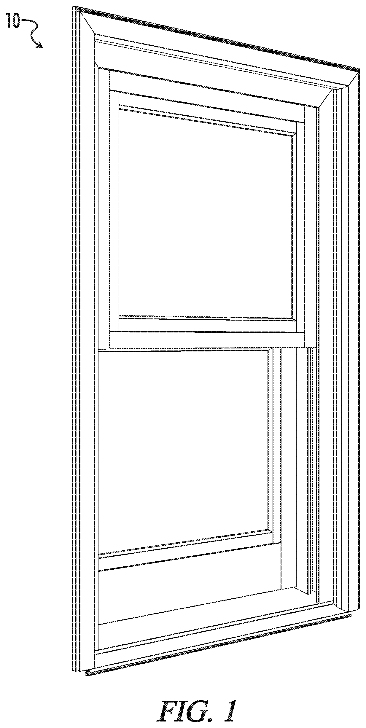
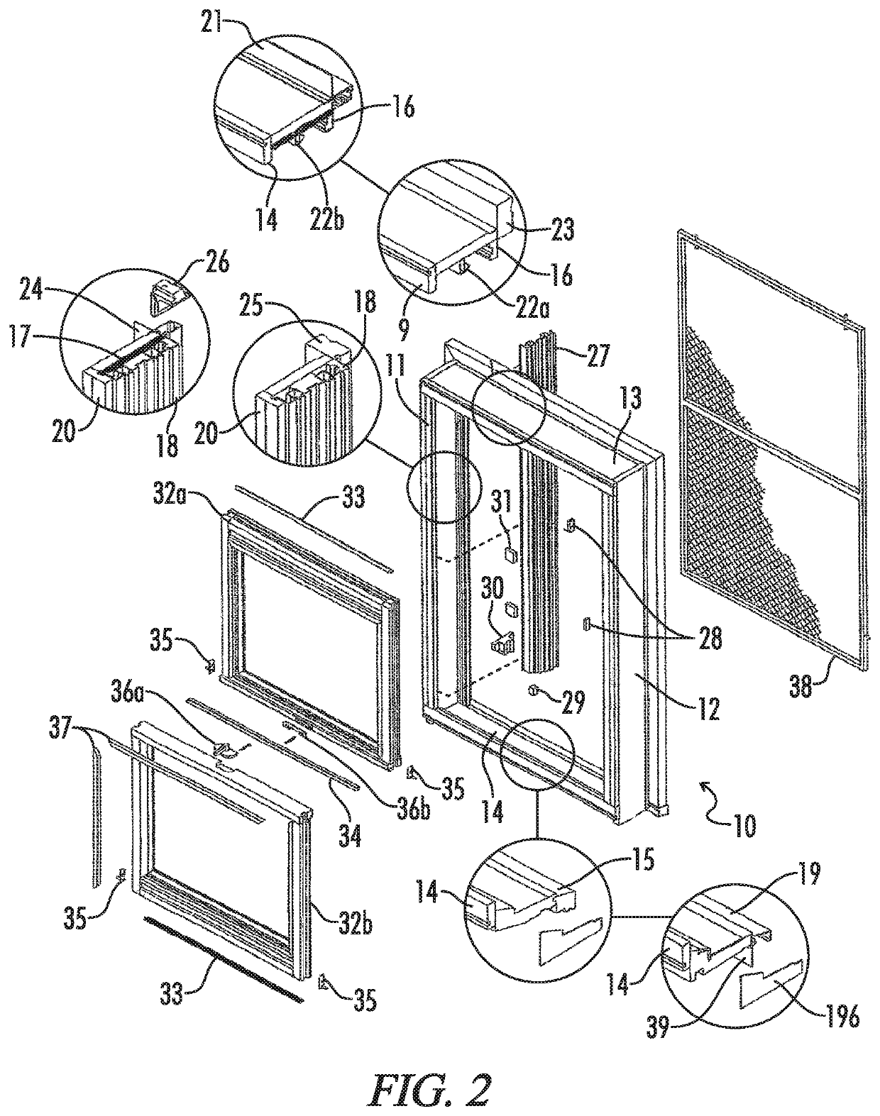
[0019]FIG. 1 illustrates an embodiment of a new exterior replacement window unit 10 manufactured in accordance with the...


PUM

PropertyMeasurementUnit
Angleaaaaaaaaaa

Abstract

A window unit and replacement window cladding method and system which is provided as a single unit to be installed as a complete new window that fits over the head, side jamb and sill of an existing window frame and the old window frame that is cladded with head jamb, side jamb, and sill cover assemblies defining an opening in which one or more sash units is pivotally secured forming a replacement window unit, without any loss of glass size and egress, and without disturbing the building interior.

Description

FIELD OF THE INVENTION[0001]The present invention relates to window constructions and cladding systems for windows, and more particularly to a method and system for installing replacement windows and cladding existing window frames.BACKGROUND OF THE INVENTION[0002]It is often desired to update or remodel dwellings and structures by replacing the original or existing windows with new, more energy efficient windows. Current methods of replacement window installation may require removal of the entire old window unit including the original frame, or may utilize the original window frame and insert another window unit having its own frame inside the original frame or sash pocket. In one current method, a bent coil stock is applied over the old exterior wood, a bead of sealant is applied around the inside perimeter of the old blind stop, and the new window and frame is then set in the old frame.[0003]A drawback of window replacement using a window unit having its own frame is that it crea...

Claims


Application Information

Patent Timeline
IPC IPC(8): E06B1/02E06B1/26E06B3/44E06B1/36E06B1/70
CPCE06B3/4415E06B1/02E06B1/36E06B1/26E06B1/702E06B2003/4461E06B1/345E06B1/6015
Inventor PIGOTT, JR., JAMES PATRICK
Owner PIGOTT AGENCY LLC
Learn More