
Method for operating a long stator linear motor

a stator linear motor and long-range technology, applied in adaptive control, process and machine control, instruments, etc., can solve the problems of grave limitations in the flexibility of continuous conveyors, different friction forces, and inability to individually transport individual transport units, so as to improve the control response. effect of control

Active Publication Date: 2020-02-04
B&R IND AUTOMATION GMBH
View PDF23 Cites 2 Cited by
  • Summary
  • Abstract
  • Description
  • Claims
  • Application Information

AI Technical Summary

Benefits of technology

This approach enables faster and more precise control interventions, reduces maintenance needs, and improves system performance by adapting to varying conditions, enhancing the dynamic control and reducing wear-related resistance.

Problems solved by technology

With this kind of conventional continuous conveyors flexibility is gravely limited, in particular an individual transport of individual transport units is not possible.
For example, the transport units may be differently loaded, may have different wear conditions, may cause different guiding forces due to manufacturing imperfections, may cause different friction forces, etc.
This kind of control does however reduce the dynamic, whereby rapid control interventions, for example a brisk speed variation of transport unit, are limited.
The individual transport units are also subject to different wear, which makes the maintenance of the transport units or the long stator linear motor complicated.
The maintenance or even the replacement of all transport units at predetermined time intervals is in fact possible and simple, but also time consuming and costly, since transport units may possibly be serviced or replaced, which do not really require such interventions.
On the other hand a higher wear may increase the resistance to movement of individual transport units due to increasing friction between the transport units and the guide.
This would cause higher performance losses, since the driving power of the transport units has to be increased.
Not in the least, the current wear condition of the transport unit influences also its control.

Method used


Image

  • Method for operating a long stator linear motor
  • Method for operating a long stator linear motor
  • Method for operating a long stator linear motor

Examples


Embodiment Construction

[0011]Embodiments of the present invention therefore better adapt the operation of a long stator linear motor to the requirements or the conditions of the individual transport units or transport track.

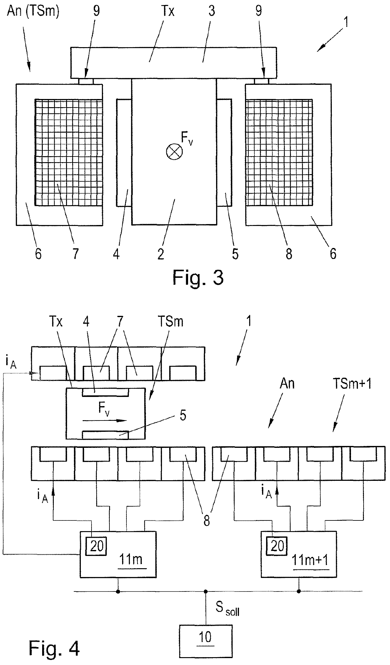
[0012]These embodiments are achieved, according to the invention by superimposing an excitation signal with a predetermined frequency band on the control variables of a driving coil, wherein actual values of the driving coil control are determined and from the control variables superimposed with the excitation signal and from the determined actual values a frequency response is determined, wherein from the frequency response the control parameters for said transport unit are determined and the transport unit is controlled using these determined control parameters for movement along the transport track. This allows a simple determination of optimized control parameters of the driving coil controller, which in turn allows for faster control interventions.

[0013]In a preferred embodiment, ...


PUM


Abstract

In order to improve the adaptation of a long stator linear motor to requirements or conditions of individual transport units or of the transport track it is foreseen, that the control variables (StG) of a driving coil (7, 8) of long stator linear motor are superimposed with an excitation signal (AS) with a predetermined frequency band, wherein actual variables (IG) of the driving coil control are determined, from the control variables (StGAS) superimposed with the excitation signal (AS) and from the determined actual variables (IG) a frequency response is determined and from the frequency response the control parameters (RP) for this transport unit (Tx) are determined and the transport unit (Tx) is controlled using these determined control parameters (RP) for movement along the transport track.

Description

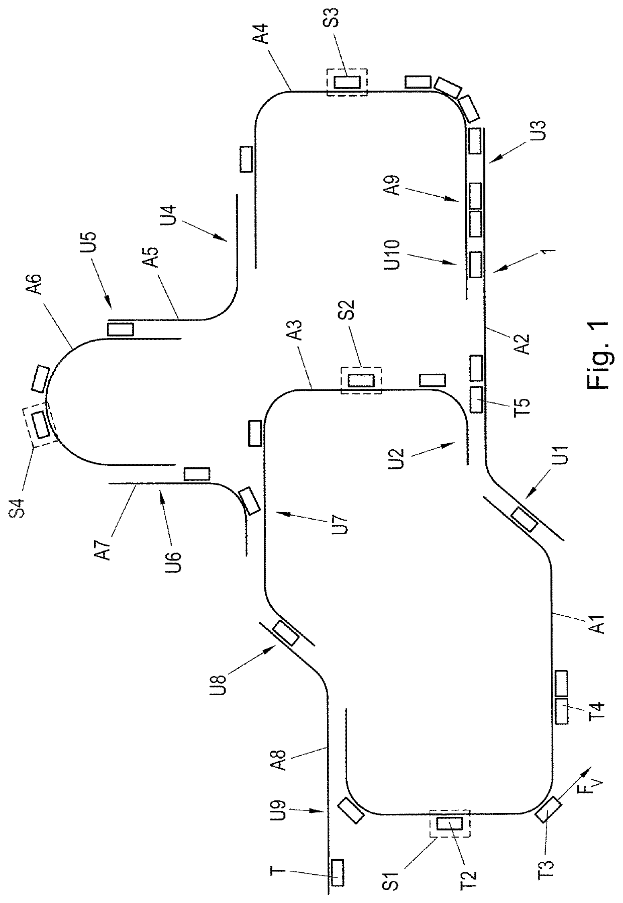
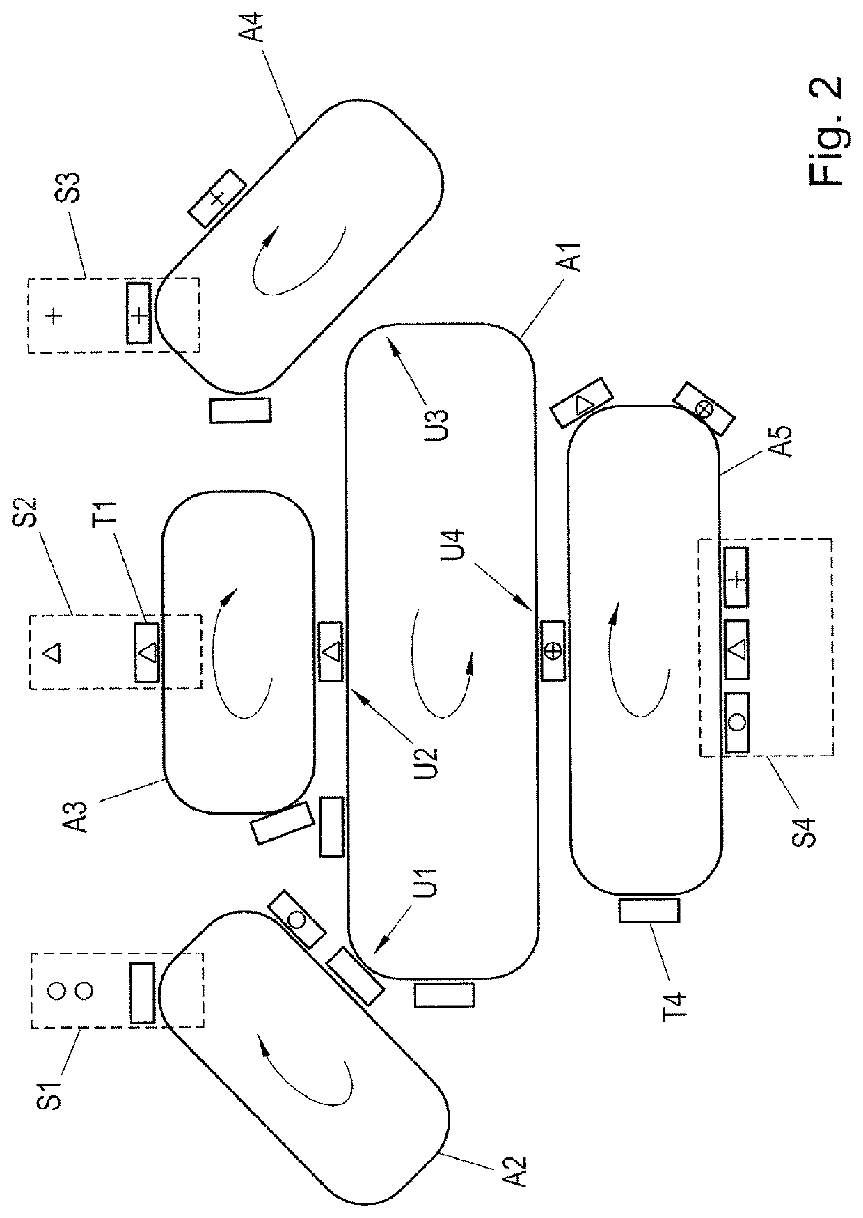
CROSS-REFERENCE TO RELATED APPLICATIONS[0001]The present application claims priority under 35 U.S.C. § 119(a) of Austria Patent Application No. A50495 / 2016 filed May 31, 2016, the disclosure of which is expressly incorporated by reference herein in its entirety.BACKGROUND OF THE INVENTION1. Field of the Invention[0002]The present invention refers to a method for operating a long stator linear motor with a transport track along which a plurality of driving coils are sequentially arranged and with at least one transport unit, which is moved along the transport track, wherein each driving coil is controlled by a driving coil controller with corresponding control parameters, in that the driving coil controllers set control variables for the driving coils interacting with the transport unit.2. Discussion of Background Information[0003]In almost every modern production plant it is required to move parts or components also over long transport distances, by means of transport apparatus, bet...

Claims


Application Information

Patent Timeline
Patent Type & Authority Patents(United States)
IPC IPC(8): H02K11/30H02K41/03B65G54/02B60L15/38B60L15/00B60L13/10H02K41/02
CPCB60L15/005H02K11/30B60L15/38B65G54/02B60L13/10H02K41/031H02K41/02H02K41/03H02K41/033H02P25/06G05B13/02G05B13/021G05B13/024B60L2240/429Y02T10/64
Inventor WEBER, ANDREASWEISSBACHER, JOACHIM
Owner B&R IND AUTOMATION GMBH
Learn More