
Light source module and backlight unit including the same

a technology of light source modules and backlight units, applied in the direction of planar/plate-like light guides, instruments, mechanical devices, etc., can solve the problems of increasing costs, achieve the effects of improving heat radiation effect, reducing the number of light sources, and improving light incident efficiency

Active Publication Date: 2020-01-21
LG DISPLAY CO LTD
View PDF2 Cites 0 Cited by
  • Summary
  • Abstract
  • Description
  • Claims
  • Application Information

AI Technical Summary

Benefits of technology

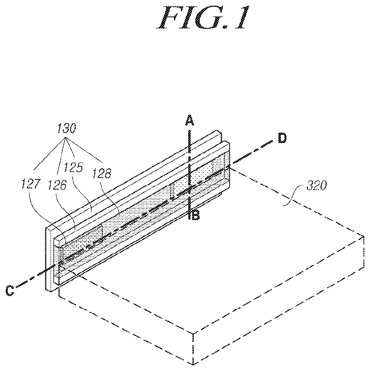
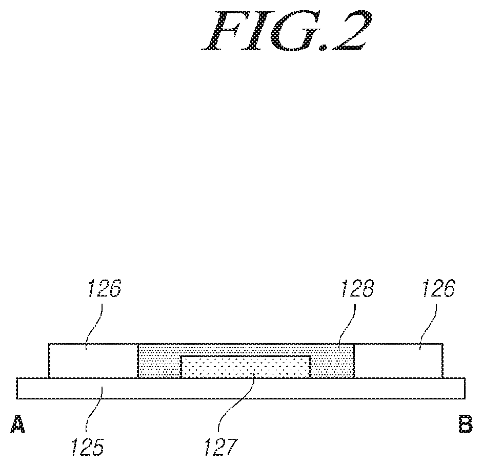
[0012]In order to solve the above-described problems, the present embodiments provide a light source module that increases the amount of light incident on a light guide plate from a light source by utilizing a total-reflection induction layer having a flat upper surface and that has a superior heat radiation effect, and further provide a backlight unit including the same.
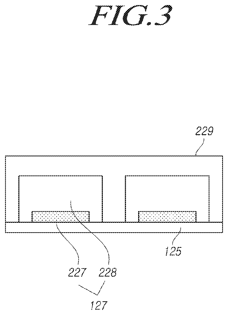
[0015]The light source module and the backlight unit including the same according to the present embodiments can improve the light incident efficiency by totally reflecting light that is not incident on the light guide plate among the light emitted from a light source by the total-reflection induction layer in order to thereby change a path of the light toward the light guide plate, thereby reducing the number of light sources that are needed to provide a sufficient amount of light through the light guide plate.
[0016]In addition, the light source module and the backlight unit including the same according to the present embodiments have an effect of improving the heat radiation effect by disposing the total-reflection induction layer on the light source package including a light source.

Problems solved by technology

The point light source of the LED lamps may cause non-uniformity in the amount of light incident on one side of the light guide plate.
However, in this case, heat generated from the LEDs may cause problems, and an increase in the number of LEDs may cause an increase in the cost.

Method used


Image

  • Light source module and backlight unit including the same
  • Light source module and backlight unit including the same
  • Light source module and backlight unit including the same

Examples


Embodiment Construction

[0026]Hereinafter, embodiments of the present disclosure will be described in detail with reference to the accompanying drawings. The following embodiments are provided, by way of example, so that the idea of the present disclosure can be sufficiently understood by those skilled in the relevant art. Therefore, the present disclosure is not limited to the embodiments as described below, and may be embodied in other forms. Also, in the drawings, the size, thickness, and the like of a device may be exaggeratedly represented for the convenience of description. Throughout the specification, the same reference numerals designate the same elements.

[0027]The advantages and features of the present disclosure and methods of achieving the same will be apparent by referring to embodiments of the present disclosure as described below in detail in conjunction with the accompanying drawings. However, the present disclosure is not limited to the embodiments set forth below, but may be implemented i...


PUM

PropertyMeasurementUnit
distanceaaaaaaaaaa
distanceaaaaaaaaaa
refractive indexaaaaaaaaaa

Abstract

The present disclosure provides a light source module that includes a substrate, a plurality of light barriers on a surface of the substrate and spaced apart from each other, a plurality of light source packages on the surface of the substrate and positioned between the plurality of light barriers, and a total-reflection induction layer on the plurality of light source packages. The total-reflection induction layer has a flat surface opposite the plurality of light source packages. According to the various embodiments provided herein, the amount of light incident on a light guide plate increases, and a heat radiation effect is improved.

Description

CROSS REFERENCE TO RELATED APPLICATION[0001]This application claims priority from Korean Patent Application No. 10-2016-0097507, filed on Jul. 29, 2016, which is hereby incorporated by reference for all purposes as if fully set forth herein.BACKGROUND[0002]Technical Field[0003]The present disclosure is generally directed to light source modules and backlight units including the same.[0004]Description of the Related Art[0005]In general, a liquid crystal display (LCD) is a kind of flat panel display, which displays images using electrical and optical characteristics of a liquid crystal that has physical characteristics between a liquid and a solid. The liquid crystal display is thin and light compared to other displays, and is widely used in many industries with various applications thanks to low power consumption and low driving voltage.[0006]Meanwhile, the liquid crystal display requires a separate light source because it is a non-light-emitting device that emits light by means of e...

Claims


Application Information

Patent Timeline
Patent Type & Authority Patents(United States)
IPC IPC(8): F21V8/00H01L33/50H01L33/60
CPCH01L33/507G02B6/0073G02B6/0068H01L33/502H01L2933/0041H01L33/60G02F1/133605G02F1/133628G02B6/0023G02B6/0031H01L25/0753G02B6/0018G02B6/0085G02B6/10G02B6/3522G02B2006/12071
Inventor KONG, CHANG KYEONGKWEON, YOUNG MINKIM, JINHO
Owner LG DISPLAY CO LTD
Learn More