Gas turbine membrane seal

a technology of membrane seals and gas turbines, applied in the direction of leakage prevention, combustion process, combustion apparatus, etc., can solve the problems of membrane seals that are more prone to fretting wear, membrane seals that are often replaced during use, and anti-fretting parts, which are generally cheaper, and remain unworn. , to achieve the effect of reducing maintenance costs, reducing membrane replacement frequency, and good membrane li

Active Publication Date: 2020-01-14
ANSALDO ENERGIA SWITZERLAND AG
View PDF34 Cites 1 Cited by
  • Summary
  • Abstract
  • Description
  • Claims
  • Application Information

AI Technical Summary

Benefits of technology

[0004]In a membrane seal where the curved surface is on the membrane and the flat surface is on the adjacent gas turbine component, the curved surface of the membrane is always in contact with the adjacent gas turbine component, and will therefore always be in a position to wear. In other words, the curved surface of the membrane is subjected to a higher contact sliding distance during operation compared to the flat contact surface on the anti-fretting part (fretting ring) and thus is more prone to fretting wear. As a result, membrane seals can require frequent replacement during use due to high rates of wear, while the anti-fretting part, which is generally cheaper, remains unworn.
[0005]In contrast, a membrane seal as described above provides the curved surface (convex surface) on an anti-fretting ring on the gas turbine component, and therefore it is the anti-fretting part that is always in contact with the membrane and liable to wear. This can reduce the membrane replacement frequency, and can provide good membrane lifetime despite high contact pressure and large relative gas turbine component displacement. This can reduce maintenance costs as it is generally cheaper to replace an anti-fretting ring than to replace a membrane.
[0006]The sealing efficiency of contact surfaces between the membrane and the anti-fretting ring normally depends on the surface condition, and it is therefore generally preferable to minimise wear and thereby minimise leakage. The present design can provide reduced wear and therefore reduced leakage, which can improve engine efficiency and power.
[0009]Preferably, at least the face of the anti-fretting part is made of a softer material than the membrane. This can reduce membrane wear, as the anti-fretting part has lower wear resistance and will wear more than the membrane.

Problems solved by technology

In other words, the curved surface of the membrane is subjected to a higher contact sliding distance during operation compared to the flat contact surface on the anti-fretting part (fretting ring) and thus is more prone to fretting wear.
As a result, membrane seals can require frequent replacement during use due to high rates of wear, while the anti-fretting part, which is generally cheaper, remains unworn.

Method used


Image

  • Gas turbine membrane seal
  • Gas turbine membrane seal
  • Gas turbine membrane seal

Examples


Embodiment Construction

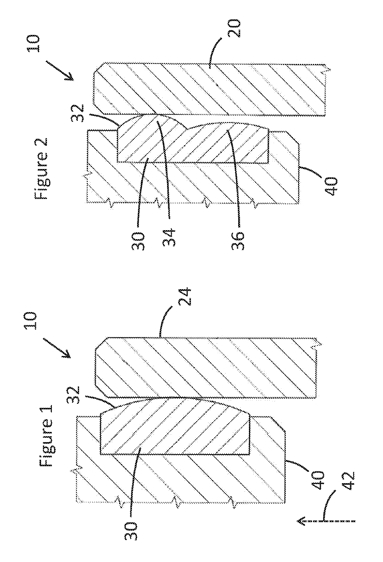
[0021]FIG. 1 shows a membrane seal 10 (also known as a cavity splitter or a large cavity splitter) comprising a membrane 20 and an anti-fretting part 30, such as an anti-fretting ring or an anti-fretting ring section. The membrane 20 adjacent to a face 32 of the anti-fretting ring 30; the face 32 is convex. The anti-fretting ring is attached to a first gas turbine component 40.

[0022]FIG. 2 shows a membrane seal 10 with a different anti-fretting ring 30. The face 32 of the anti-fretting ring shown in FIG. 1 is convex with a single convex portion; the membrane seal of FIG. 2 has a first convex portion 34 and a second convex portion 36. The first convex portion 34 is in contact with the membrane 20, and the second convex portion 36 is spaced apart from the membrane 20.

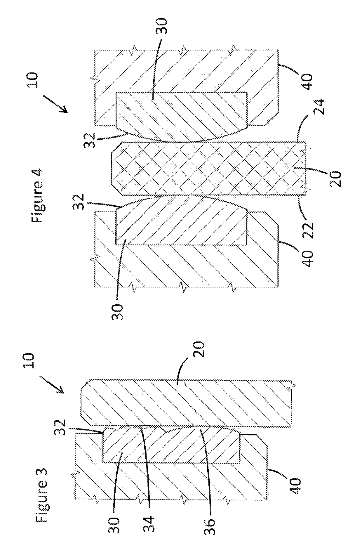
[0023]When in use, the first convex portion 34 may become worn as shown in FIG. 3. After a certain amount of wear of the first convex portion 34, the second convex portion 36 is also in contact with the membrane.

[0024]FIG...


PUM


Abstract

A gas turbine membrane seal is disclosed. The gas turbine membrane seal includes a membrane, the membrane configured and arranged to extend from a first gas turbine component to a second gas turbine component and to separate two volumes, and an anti-fretting part configured and arranged to be attached to the first gas turbine component. A face of the anti-fretting part is adjacent to the membrane, and the face of the anti-fretting part is convex. Further embodiments of the gas turbine membrane seal are also described, along with a gas turbine having the gas turbine membrane seal and a retrofitting method.

Description

TECHNICAL FIELD[0001]The present disclosure relates to gas turbine membrane seals, and particularly to gas turbine membrane seals with a membrane and an anti-fretting part.BACKGROUND OF THE INVENTION[0002]Modern gas turbines are extremely complex and include a large number of seals to reduce leakage through various cavities and gaps, helping to control flow of the various fluids around the gas turbine. One such type of seal is the membrane seal, and U.S. Pat. No. 6,857,849, a granted patent assigned to the current applicant, shows an example of a known membrane seal. Known membrane seals such as that described in U.S. Pat. No. 6,857,849 can provide an effective seal, but tend to have a relatively short lifetime and can often require replacing due to wear. The replacement frequency is greater when the sliding distance and pressure difference at the side of membrane is relatively high. It has therefore been appreciated that the existing designs can be further improved.SUMMARY OF THE I...

Claims


Application Information

Patent Timeline
Patent Type & Authority Patents(United States)
IPC IPC(8): F01D11/00F16J3/02F01D25/24F23R3/60
CPCF01D11/003F01D11/005F23R3/60F01D25/246F16J3/02F05D2240/35F05D2250/711F05D2230/80F05D2220/32
Inventor MALEKI, MILADPRZYBYL, ROBERTHUBER, THOMAS
Owner ANSALDO ENERGIA SWITZERLAND AG
Why Eureka
Try Eureka