Tip structure for a turbine blade with pressure side and suction side rails

a turbine blade and tip structure technology, applied in the direction of machines/engines, climate sustainability, sustainable transportation, etc., can solve the problems of reducing aerodynamic performance and high heat transfer, and achieve the effect of improving the control of over-tip flow

Active Publication Date: 2020-01-14
ROLLS ROYCE CORP
View PDF32 Cites 1 Cited by
  • Summary
  • Abstract
  • Description
  • Claims
  • Application Information

AI Technical Summary

Problems solved by technology

Flow leakage over the tips of the airfoils may result in reduced aerodynamic performance and high heat transfer.

Method used


Image

  • Tip structure for a turbine blade with pressure side and suction side rails
  • Tip structure for a turbine blade with pressure side and suction side rails
  • Tip structure for a turbine blade with pressure side and suction side rails

Examples


Embodiment Construction

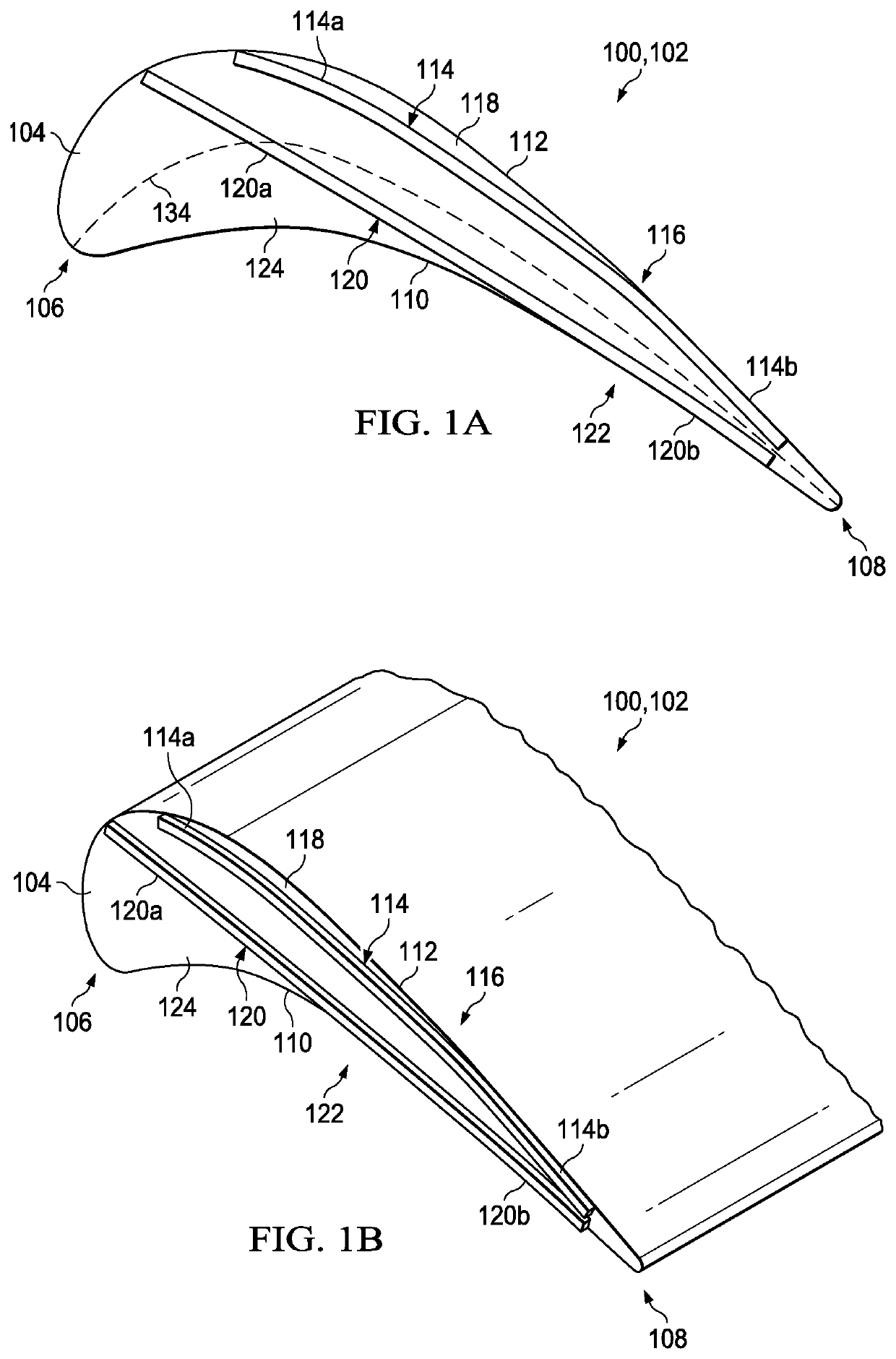
[0021]Described in this disclosure is a tip structure for a turbine blade that includes pressure and suction side rails configured to maximize aerodynamic efficiency and / or minimize heat transfer on the tip surface.

[0022]Referring first to FIGS. 1A and 1B, the tip structure 102 includes a tip surface 104 that extends from a leading edge 106 to a trailing edge 108 and from a pressure side 110 to a suction side 112 of the turbine blade or airfoil 100. A suction side rail 114 protrudes from the tip surface 104 and extends from the suction side 112 of the airfoil 100 at or near the trailing edge 108 toward the leading edge 106 in a generally chordal direction. The suction side rail 114 includes a leading portion 114a nearer to the leading edge 106 and a trailing portion 114b closer to the trailing edge. A pressure side rail 120 protrudes from the tip surface 104 and extends from the pressure side 110 of the airfoil 100 at or near the trailing edge 108 toward the leading edge 106 in a ge...


PUM


Abstract

A tip structure for a turbine blade comprises a tip surface of an airfoil that extends from a leading edge to a trailing edge and from a pressure side to a suction side of the airfoil. A suction side rail protrudes from the tip surface and comprises: a trailing portion extending flush with the suction side of the airfoil from an origination location at or near the trailing edge to an intermediate location on the suction side; and a leading portion extending from the intermediate location across the tip surface so as to create a suction side shelf region between the leading portion of the suction side rail and the suction side of the airfoil. A pressure side rail protrudes from the tip surface and comprises: a trailing segment extending flush with the pressure side of the airfoil from an origination location at or near the trailing edge to a middle location on the pressure side; and a leading segment extending from the middle location across a camber line on the tip surface so as to create a pressure side shelf region between the leading segment of the pressure side rail and the pressure side of the airfoil.

Description

RELATED APPLICATION[0001]The present patent document claims the benefit of priority under 35 U.S.C § 119(e) to U.S. Provisional Patent Application No. 62 / 463,928, on Feb. 27, 2017, which is hereby incorporated by reference in its entirety.TECHNICAL FIELD[0002]The present disclosure is directed to an airfoil for a gas turbine engine and more particularly to a tip structure configured for controlled over-tip flow and effective tip cooling.BACKGROUND[0003]Gas turbine engines include a compressor, combustor and turbine in flow series along a common shaft. Compressed air from the compressor is mixed with fuel in the combustor to generate hot combustion gases that rotate the turbine blades and drive the compressor. Flow leakage over the tips of the airfoils may result in reduced aerodynamic performance and high heat transfer. Consequently, there is significant interest in developing improved tip geometries that minimize over-tip loss while maintaining or improving tip heat transfer.BRIEF ...

Claims


Application Information

Patent Timeline
Patent Type & Authority Patents(United States)
IPC IPC(8): F01D5/20
CPCF01D5/20F01D5/282F01D5/284F01D11/20F05D2300/603Y02T50/60
Inventor BLOXHAM, MATTHEW J.EBACHER, JON V.PANIAGUA PEREZ, GUILLERMOANDREOLI, VALERIADE MAESSCHALCK, CIS GUY M.BRAUN, JAMES
Owner ROLLS ROYCE CORP
Why Eureka
Try Eureka