Instrumented flow passage of a turbine engine

a turbine engine and instrument technology, applied in the direction of instruments, machines/engines, mechanical equipment, etc., can solve the problems of high risk of resonance, damage to components of the turbine engine arranged downstream, and damage caused by such dislocations to be particularly severe, so as to achieve simple, effective and economical effects

Active Publication Date: 2019-12-24
SN DETUDE & DE CONSTR DE MOTEURS DAVIATION S N E C M A
View PDF7 Cites 0 Cited by
  • Summary
  • Abstract
  • Description
  • Claims
  • Application Information

AI Technical Summary

Benefits of technology

[0036]Use of a rod mounted movably in translation allows an increase in precision of control of the natural frequencies by shifting the center of gravity of the element along the entire length of the element. The rod may be hollow or solid. This embodiment also proves easier to realise, since it does not require any connected tanks or duct with leaktightness that may be difficult to achieve.
[0038]Use of means of measurement allows precise positioning of the mass inside the cavity, which permits precise modification of the resonance frequency.
[0042]These weights serve to restrict formation of normal modes of the rod by increasing the overall rigidity of the rod. These weights may also be evenly spaced.
[0055]The method according to the invention allows, using means of modification of the center of gravity position, modification of the natural frequency fr1 of the element such that this frequency is sufficiently distanced from the vibration frequency f1 depending on the element. It is thus possible to limit the risks of resonance of the element.
[0057]Such a method makes it possible to control the natural frequencies fr<sub2>i < / sub2>of the element taking account of the excitation frequency f1 of the element during operation.

Problems solved by technology

The debris thus released circulates in the flow passage and may damage components of the turbine engine arranged downstream.
It is clear that the damage caused by such dislocation may be particularly severe when a measuring element 42a, 42b, 42c is installed in the primary flow passage, since the debris pay damage the combustion chamber and the fixed and rotating components of the high-pressure and low-pressure turbines.
A first source of vibration results for example from the residual imbalance of the rotating assemblies, i.e. of the low-pressure and high-pressure rotors.
If the first normal mode of the measuring element is close to 1000 Hz, the element will have a high risk of resonating in this case.
When the vibration frequency of the element f1 comes close to its resonance frequency fr1, there is a high risk of resonance, which increases the risk of crack formation.
In other words, some ranges of operating speeds of the turbofan may be prohibited in the presence of the measuring element, thereby reducing the value of the engine trials.
Stoppage of the test turbine engine may therefore be necessary in order to change the element, which results in an increase in costs.

Method used


Image

  • Instrumented flow passage of a turbine engine
  • Instrumented flow passage of a turbine engine
  • Instrumented flow passage of a turbine engine

Examples


first embodiment

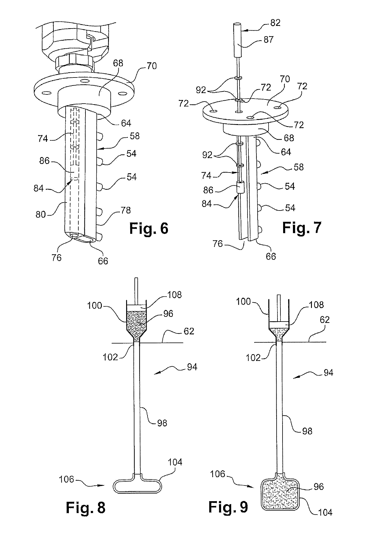
[0070]In the invention, the means of movement of a mass comprise a rod 74 mounted movably in translation in a cavity 76 of the element 58. The element 58 comprises a first upstream portion 78 comprising the holes for passage of nozzles 54 for measuring the characteristics of a flow, wherein these nozzles 54 comprise an opening oriented in the upstream direction and a downstream portion 80 accommodating the tubular-shaped cavity 76 in which the rod 74 is able to slide. It will be noted that the external surface of the downstream 78 and upstream 80 portions have an aerodynamic profile adapted to passage of an air flow so as to limit the impact of the measuring element 58 in the air flow.

[0071]The rod 74 comprises a first radially external end 82 and a second end 84, radially internal. The second end 84 bears a mass 86 which is an appreciably cylindrical-shaped solid. The first end 82 of the rod passes through the external wall 62 and comprises a cylindrical portion 87 of larger diamet...

second embodiment

[0078]FIGS. 8 and 9 illustrate the invention in which the center of gravity of the element 94 is shifted by means of a liquid mass 96 movable between a first position (FIG. 8) and a second position (FIG. 9). To this end, the element 94 comprises at least one duct 98 providing a leaktight connection between a first external tank 100 arranged outside the external wall 62, at the first end 102 of the element 94 and a second tank 104 arranged at the second end 106 of the element 94.

[0079]The first tank 100 comprises a rigid jacket forming a body in which a piston 108 is slidably installed for transferring the liquid between the first 100 and second 104 tanks. The second tank 104 comprises a flexible jacket arranged at the second end 106 of the element 94.

[0080]Use of a slidably installed piston 108 simplifies the liquid displacement device, generating a vacuum at the piston 108, to a mere movement of the piston 108. The piston 108 may be movable among several positions so as to displace...


PUM


Abstract

An annular air flow passage includes two radially internal and external annular walls. An element is elongated in a direction between the internal and external annular walls and a first of the internal or external ends of the element is fixed rigidly to a first of the internal or external walls. The center of gravity position of the element is variable.

Description

BACKGROUND OF THE INVENTION[0001]1. Field of the Invention:[0002]The present invention concerns an annular air flow passage, particularly for a turbine engine, such as a turbofan or turboprop, comprising an elongated element passing through the flow passage and capable of being instrumented.[0003]2. Description of the Related Art:[0004]Conventionally, a dual-flow turbofan 10, as illustrated in FIG. 1, consists of a gas turbine 12 with a revolution axis 14 driving a ducted fan wheel 16, wherein the latter is generally positioned upstream from the turbofan. The mass of air sucked in by the engine is divided into a primary air flow (arrow A) that flows through the gas turbine 12 or engine core and a secondary air flow (arrow B) originating from the fan 16 and surrounding the engine core, wherein the primary and secondary air flows are concentric and circulate in a primary annular flow passage 18 and a secondary annular flow passage 20 respectively 8.[0005]In a manner well known per se,...

Claims


Application Information

Patent Timeline
Patent Type & Authority Patents(United States)
IPC IPC(8): F01D17/02G01P5/165F01D5/26
CPCF01D17/02F01D5/26G01P5/165F05D2260/83F05D2260/961F05D2260/80Y02T50/671Y02T50/673F05D2260/12Y02T50/60
Inventor GIORDAN, JEREMYKOCKENPO, FLORIAN JOSEPH BERNARDROUSSELIN, STEPHANE
Owner SN DETUDE & DE CONSTR DE MOTEURS DAVIATION S N E C M A
Why Eureka
Try Eureka