Pneumatic tire

a technology of pneumatic tires and tyres, which is applied in the direction of tyre tread bands/patterns, vehicle components, transportation and packaging, etc., can solve the problems of steering stability, temperature has not been taken into account, and the warm-up performance of elevating a temperature of a tread portion, so as to reduce the rigidity of the shoulder block, the effect of easy deformation and easy elevation

Active Publication Date: 2019-12-03
TOYO TIRE & RUBBER CO LTD
View PDF6 Cites 0 Cited by
  • Summary
  • Abstract
  • Description
  • Claims
  • Application Information

AI Technical Summary

Benefits of technology

[0006]It is an object of the present invention to provide a pneumatic tire which can enhance both a warm-up performance and a steering stability.
[0008]With such a configuration, when the tread portion is brought into contact with a ground, the shoulder block is easily deformable in the shoulder region and hence, the generation of heat is promoted in the shoulder region whereby a warm-up performance can be enhanced. On the other hand, the ribs are formed in the center region and hence, the tread portion can maintain desired rigidity whereby the pneumatic tire can acquire an excellent steering stability.
[0010]With such a configuration, rigidity of the pneumatic tire in the shoulder region can be enhanced so that a cornering performance of the pneumatic tire can be enhanced.
[0012]With such a configuration, heat generated in the shoulder block can be easily transferred to the center region side or to the outside of the shoulder region in the tire width direction and hence, the generation of heat over the entire tread portion can be made uniform and effective.
[0014]With such a configuration, the deformation of the shoulder block which is brought about when the shoulder block is brought into contact with a ground at a corner portion inside or outside in the tire width direction is supported by a land portion disposed adjacently to the shoulder block and hence, lowering of rigidity of the shoulder block can be suppressed.
[0015]According to the present invention, with the formation of the shoulder block in the shoulder region, the tread portion is easily deformable at the time of contacting a ground and hence, a temperature of the tread portion can be easily elevated earlier whereby a warm-up performance of the pneumatic tire can be enhanced. Further, with the formation of the rib in the center region, rigidity of the pneumatic tire at the time of contacting the ground can be maintained whereby steering stability of the pneumatic tire can be enhanced.

Problems solved by technology

However, in the above-mentioned both pneumatic tires, a warm-up performance for elevating a temperature of a tread portion earlier in a traveling start stage has not been taken into consideration.
Further, a steering stability when a warm-up performance is enhanced has not been also taken into consideration in these pneumatic tires.

Method used


Image

  • Pneumatic tire
  • Pneumatic tire
  • Pneumatic tire

Examples


Embodiment Construction

[0020]Hereinafter, an embodiment of the present invention is described with reference to attached drawings. In the description made hereinafter, terms indicative of specific directions and positions (for example, terms including “up”, “down”, “side”, and “end”) are used when necessary. However, these terms are used for merely facilitating understanding of the invention with reference to drawings, and the technical scope of the present invention is not limited by meaning of these terms. Further, the description made hereinafter merely shows an example essentially, and does not intend to limit the present invention, products to which the present invention is applied, or its applications. Further, drawings are schematically shown and hence, ratios of respective sizes and the like may differ from actual ratios of sizes and the like.

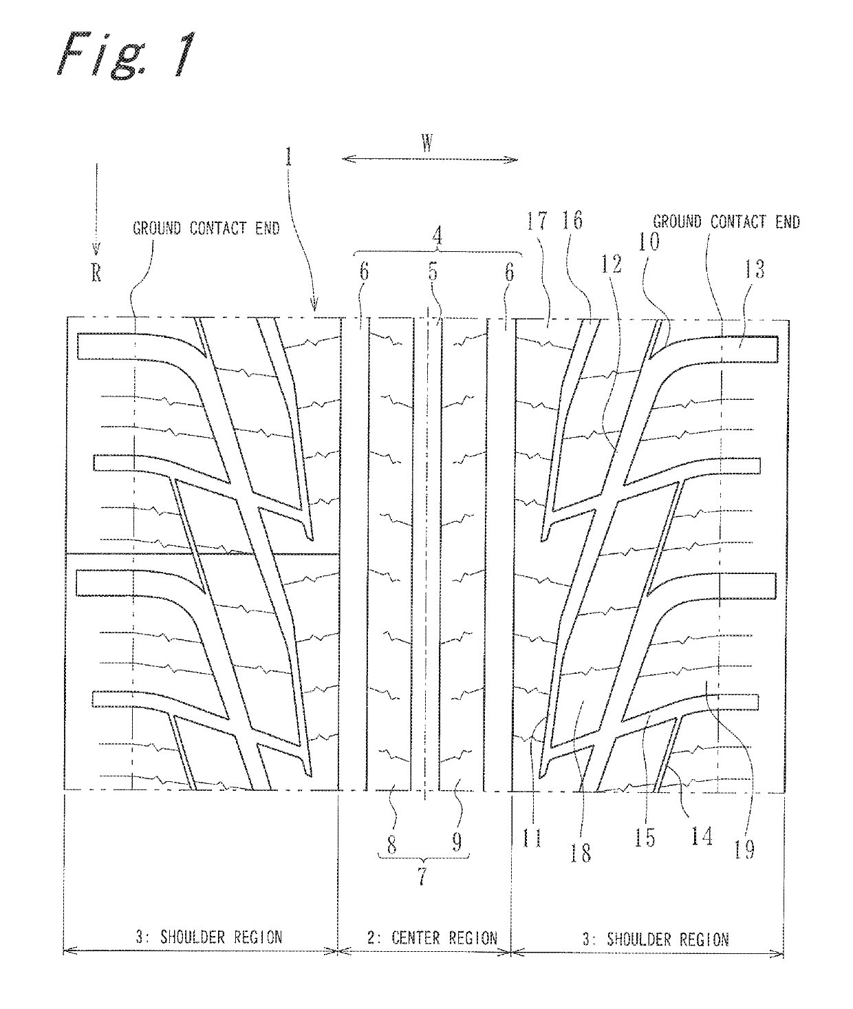
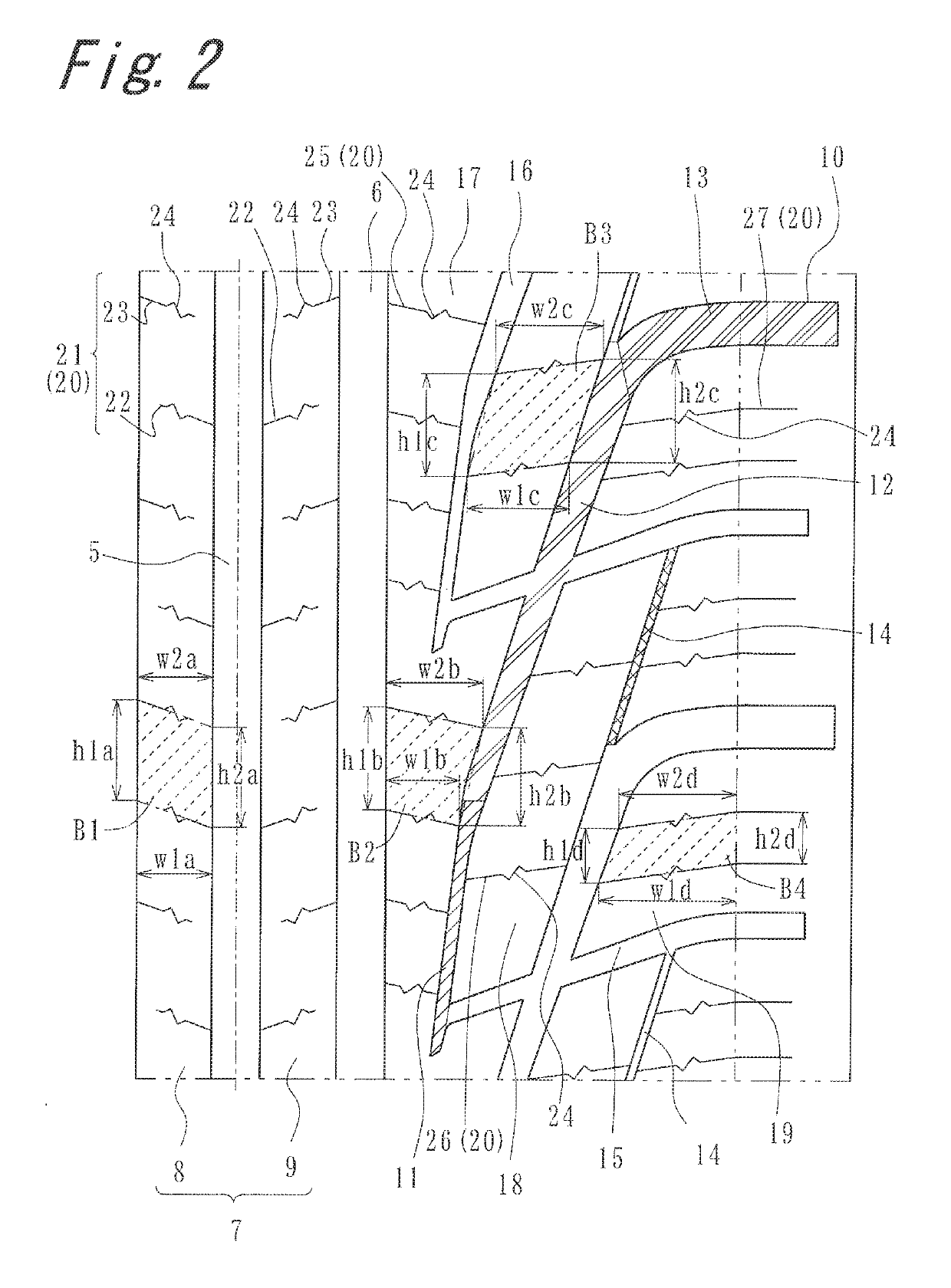
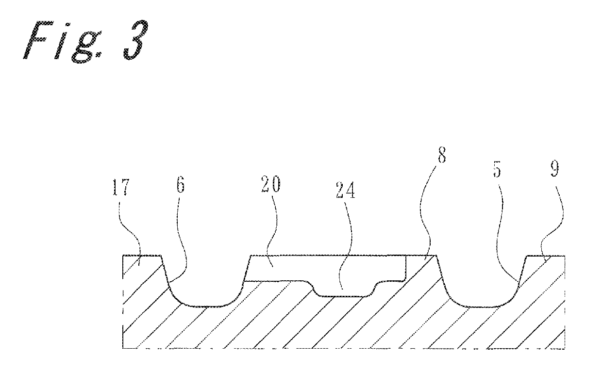
[0021]FIG. 1 is a developed view showing a portion of a tread portion 1 of a pneumatic tire according to the embodiment of the present invention. Although no...


PUM


Abstract

A tread portion of a pneumatic tire is divided into a center region at a center portion in a tire width direction and shoulder regions disposed on both sides of the center region. Each of the center region includes ribs which are formed by a plurality of main grooves extending in a tire circumferential direction. The shoulder region includes: a plurality of inclined grooves which are inclined toward the outside in a tire width direction and toward a direction opposite to a tire rotational direction at the time of advancing a vehicle; and a shoulder block surrounded by the inclined grooves.

Description

CROSS-REFERENCE TO RELATED APPLICATIONS[0001]This application claims priority of Japanese Patent Application No.: 2016-152998 filed on Aug. 3, 2016, the content of which is incorporated herein by reference.BACKGROUND OF THE INVENTIONTechnical Field[0002]The present invention relates to a pneumatic tire.Related Art[0003]Conventionally, as a pneumatic tire, there has been known a pneumatic tire which includes a plurality of inclined main grooves extending toward the outside in a tire width direction from an area in the vicinity of a tire equator and in an inclined manner toward a side opposite to a tire rotational direction (see JP-A-2014-181000, for example).[0004]As another pneumatic tire, there has been known a pneumatic tire where lateral grooves which communicate with main grooves and extend in an inclined manner in directions opposite to each other toward outside in a tire width direction, and bent sub grooves which do not communicate with the main grooves, intersect with one of...

Claims


Application Information

Patent Timeline
Patent Type & Authority Patents(United States)
IPC IPC(8): B60C11/03B60C11/12
CPCB60C11/0302B60C11/1236B60C11/1263B60C2011/129B60C2011/0376B60C2011/1213B60C2011/0358B60C2011/0374B60C2011/0341
Inventor YASUNAGA, TOSHIKAZU
Owner TOYO TIRE & RUBBER CO LTD
Why Eureka
Try Eureka