
Landing guidance for remotely operated aerial vehicles using crossed radar beams

a technology of radar beams and guidance lines, which is applied in the direction of using reradiation, process and machine control, instruments, etc., can solve the problems of pilots disrupting autonomous flight, uavs may or may not provide images and/or video back to the operator, and assume control of the remotely operated aerial vehicl

Active Publication Date: 2019-11-26
EL-SIGHT LTD
View PDF5 Cites 1 Cited by
  • Summary
  • Abstract
  • Description
  • Claims
  • Application Information

AI Technical Summary

Benefits of technology

The present invention relates to methods, systems, devices, apparatus, and computer programs for landing guidance for remotely operated aerial vehicles using crossed radar beams. The invention uses multiple radar units to detect the position of an aerial vehicle and calculates the difference in the energy returned by each unit to determine the vehicle's direction of motion. The invention then instructs the vehicle to maneuver in a specific direction to reduce the calculated difference. This process allows for precise guidance for safe landings. Additionally, the invention can also detect the vehicle's position on a landing structure using radar and guide the vehicle to the desired position.

Problems solved by technology

These UAVs may or may not provide images and / or video back to the operator.
When appropriate (e.g., due to component failures, weather conditions, etc.), the pilot can disrupt autonomous flight and assume control of the Remotely Operated Aerial Vehicle.

Method used


Image

  • Landing guidance for remotely operated aerial vehicles using crossed radar beams
  • Landing guidance for remotely operated aerial vehicles using crossed radar beams
  • Landing guidance for remotely operated aerial vehicles using crossed radar beams

Examples


Embodiment Construction

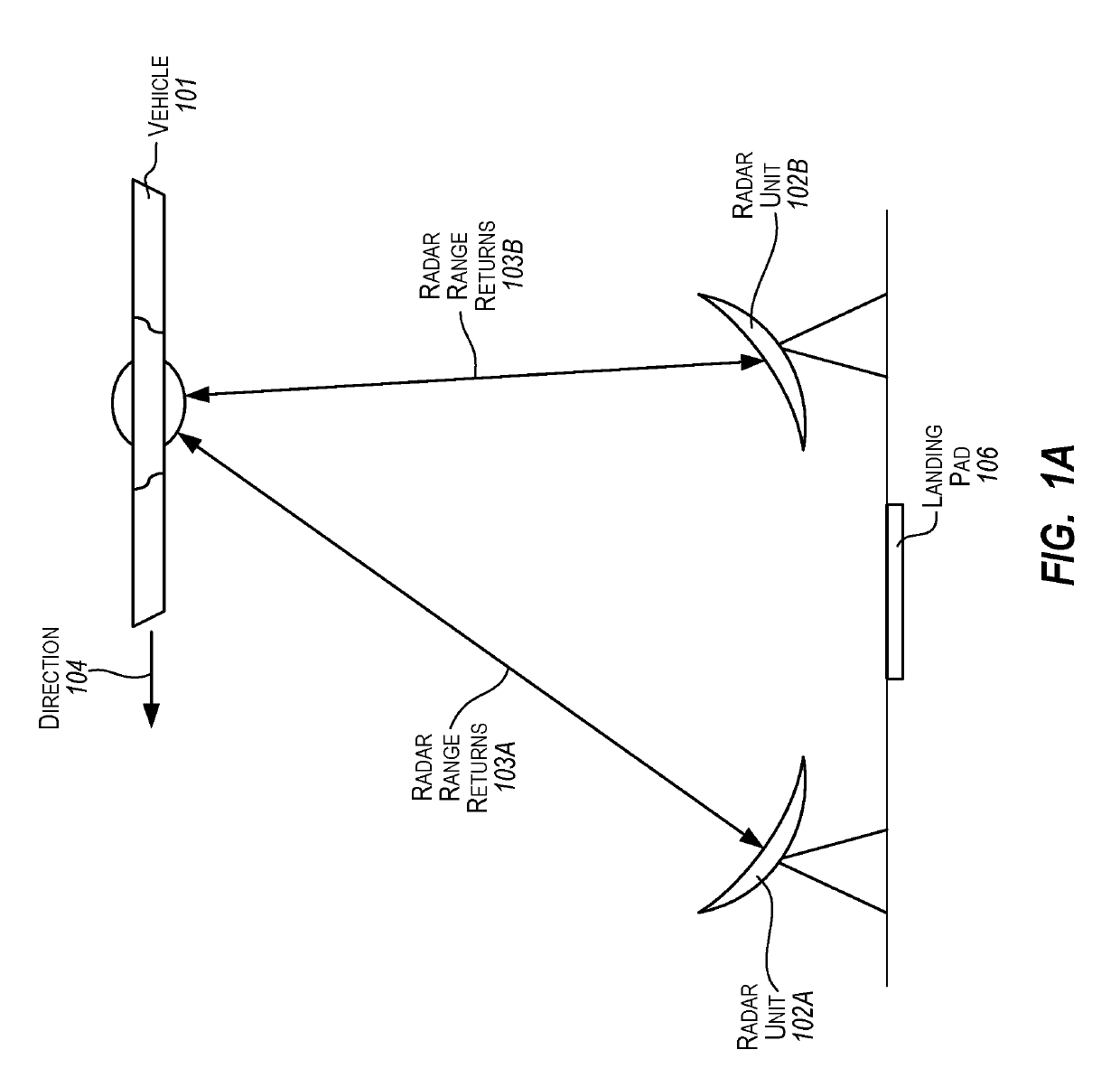
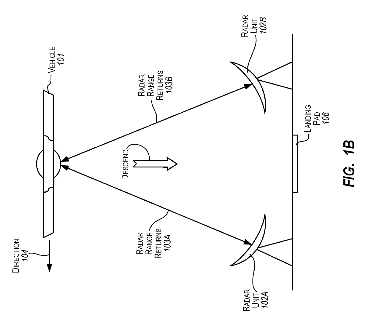
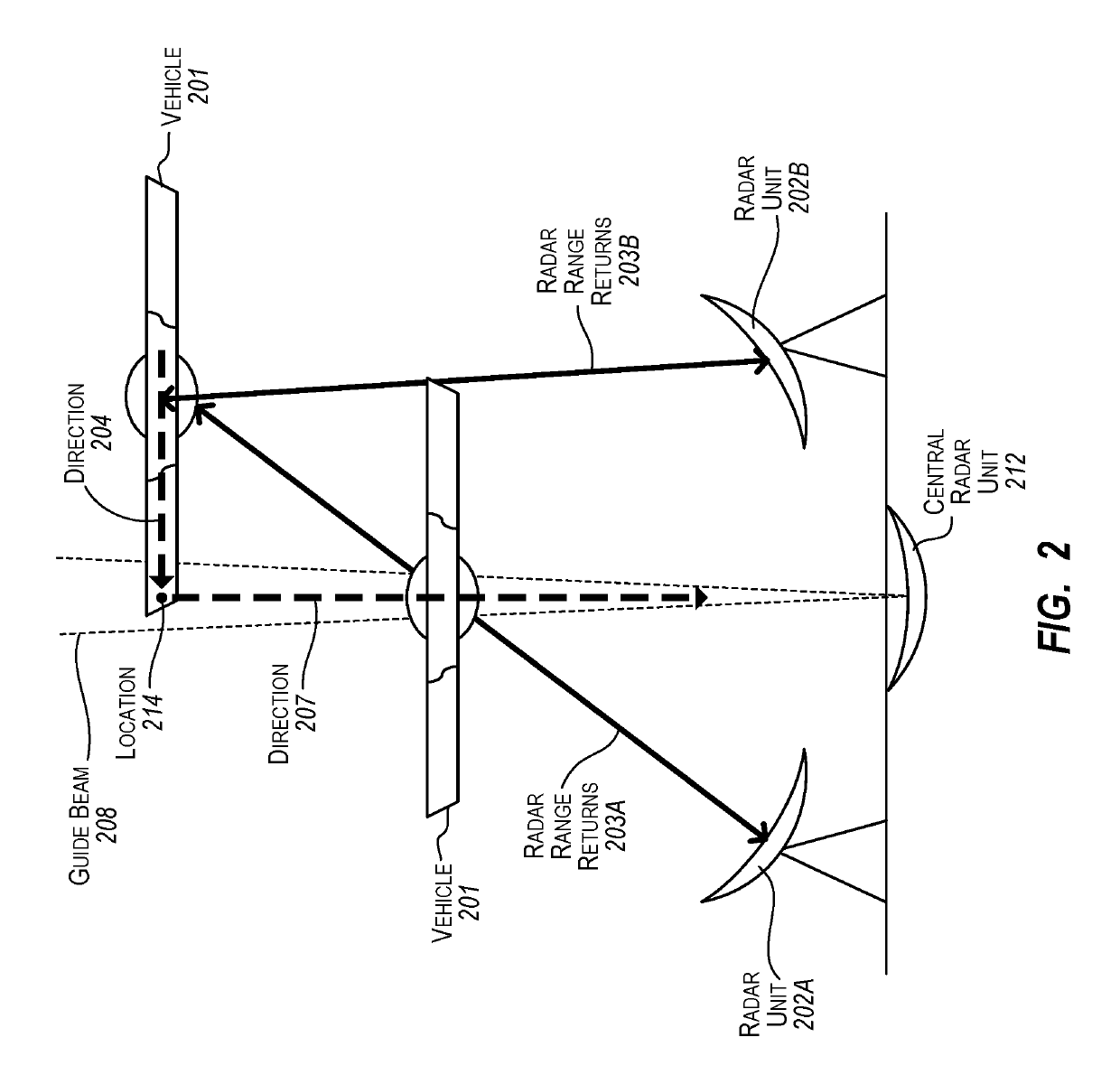
[0013]The present invention extends to methods, systems, devices, apparatus, and computer program products for landing guidance for remotely operated aerial vehicles using crossed radar beams. Radar returns are accessed from a plurality of radar units detecting a remotely operated aerial vehicle. For each of the accessed radar returns, a difference in the returned energy for the accessed radar return relative to each of the other accessed radar returns is calculated. It is determined that a calculated difference in returned energy between an accessed radar return for at least one of the plurality of radar units and an accessed radar return for at least one other of the plurality of radar units exceeds a specified threshold. A direction for the remotely operated aerial vehicle to maneuver to reduce the calculated difference is identified. The remotely operated aerial vehicle is instructed to maneuver in the identified direction.

[0014]After a maneuvering in a direction or upon initial...


PUM


Abstract

The present invention extends to methods, systems, devices, and apparatus for landing guidance for remotely operated aerial vehicles using crossed radar beams. Radar units can be angled over a landing pad / dish for a Remotely Operated Aerial Vehicle. The Remotely Operated Aerial Vehicle lines up over radar beams by basically following radar beams to equalize the returned energy of each beam. The radar units facilitate lateral position tracking. When a Remotely Operated Aerial Vehicle is off to one side, returns for one or more beams may be stronger than returns for one or more other beans. When a Remotely Operated Aerial Vehicle is maneuvered to an appropriate position for terminal guidance, rotors can be turned off and / or thrust settled (e.g., to 90%).

Description

CROSS-REFERENCE TO RELATED APPLICATIONS[0001]This application claims the benefit of and priority to U.S. Provisional Patent Application Ser. No. 62 / 320,445 entitled “Landing Guidance For Remotely Operated Aerial Vehicles Using Crossed Radar Beams”, filed Apr. 8, 2016 by Paul E. I. Pounds, the entire contents of which are expressly incorporated by reference.BACKGROUNDBackground and Relevant Art[0002]The number of remotely operated (e.g., piloted) aerial vehicles, including unmanned aerial vehicles (UAVs), being flown continues to increase. A variety of different entities including hobbyists, delivery companies, intelligence agencies, surveyors, power companies, etc. use Remotely Operated Aerial Vehicles. Some Remotely Operated Aerial Vehicles operate past line of sight. On an ongoing basis and / or at a destination, the Remotely Operated Aerial Vehicle provides images and / or video of its surroundings back to a monitoring system (which may or may not be the location of the operator). Th...

Claims


Application Information

Patent Timeline
IPC IPC(8): G01S13/91G01S13/87G05D1/00G05D1/10B64C39/02B64D45/04
CPCB64C39/024G01S13/87G05D1/101G05D1/0022B64D45/04G01S13/913B64C2201/146B64C2201/108B64C2201/027G05D1/0676G01S13/878G01S7/003B64U10/13B64U30/20B64U2201/10B64U70/95B64U2201/20
Inventor POUNDS, PAUL E. I.
Owner EL-SIGHT LTD
Learn More