
Switch disconnector systems suitable for molded case circuit breakers and related methods

a technology of switch disconnector and circuit breaker, which is applied in the field of circuit breakers, can solve problems such as impede the ability of the breaker to operate with a desired and achieve the effect of increasing the level of withstand current and reducing electromagnetic forces

Active Publication Date: 2019-11-19
EATON INTELLIGENT POWER LTD
View PDF99 Cites 5 Cited by
  • Summary
  • Abstract
  • Description
  • Claims
  • Application Information

AI Technical Summary

Benefits of technology

This patent is about circuit breakers that have a special shape that can decrease the buildup of magnetic energy during high current levels. The breaker also directs the electric current to flow along a specific path that reduces the magnetic energy and increases the ability of the breaker to handle high levels of current.

Problems solved by technology

During certain fault interruptions, high electromagnetic forces generated internally due to high current levels can impede the breaker's ability to operate with a desired level of withstand current (Icw).

Method used


Image

  • Switch disconnector systems suitable for molded case circuit breakers and related methods
  • Switch disconnector systems suitable for molded case circuit breakers and related methods
  • Switch disconnector systems suitable for molded case circuit breakers and related methods

Examples


Embodiment Construction

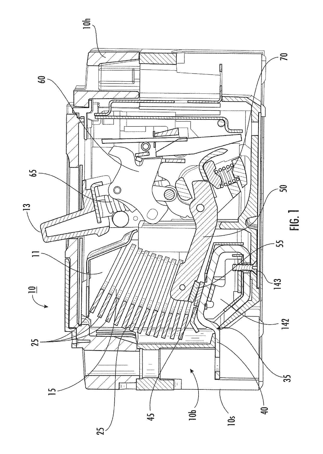
[0005]Embodiments of the present invention are directed to circuit breakers that can achieve increased, desired withstand current levels.

[0006]Embodiments are directed to molded case circuit breakers.

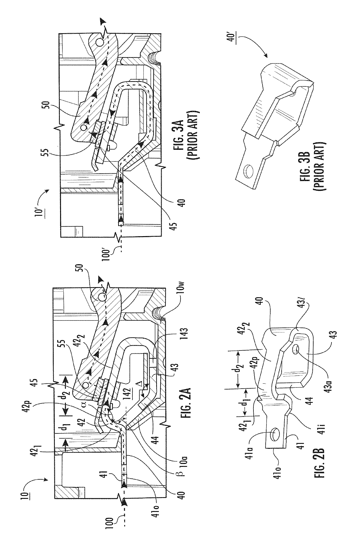
[0007]Some embodiments are directed to circuit breakers that include a geometrically shaped line terminal that can reduce electromagnetic forces generated during a high current level condition.

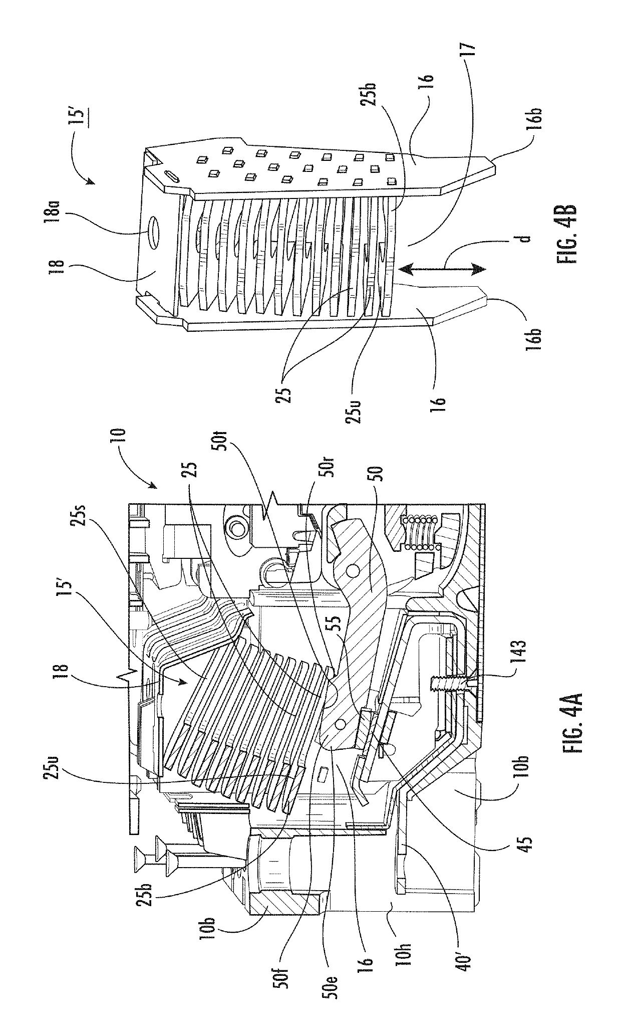
[0008]Embodiments of the invention are directed to a circuit breaker with a housing, an arc chute in the housing that includes a plurality of stacked arc chute plates. The circuit breaker also includes a movable contact arm in the housing that holds a moving contact. The circuit breaker further includes a line terminal in the housing with a terminal end portion that faces a line side of the housing. The terminal end portion merges into an arm segment that has a first portion that angles toward the moving contact at a first angle. The first portion of the arm segment merges into a second portion th...


PUM


Abstract

Circuit breakers are configured with line terminal geometry that drives the current from a terminal input in a direction that can reduce electromagnetic forces and that can also or alternatively include an arc chute assembly that can reduce repulsive electromagnetic forces to improve the operating level of withstand current (Icw).

Description

FIELD OF THE INVENTION[0001]The present invention relates to circuit breakers.BACKGROUND OF THE INVENTION[0002]Circuit breakers are one of a variety of overcurrent protection devices used for circuit protection and isolation. The circuit breaker provides electrical protection whenever an electric abnormality occurs. In a circuit breaker, current enters the system from a power line and passes through a line conductor to a stationary contact fixed on the line conductor, then to a movable contact. The movable contact can be fixedly attached to a rotatable arm. As long as the stationary and movable contacts are in physical contact, current passes from the stationary contact to the movable contact and out of the circuit breaker to down line electrical devices.[0003]In the event of an overcurrent condition (e.g., a short circuit), extremely high electromagnetic forces can be generated. The electromagnetic forces repel the movable contact away from the stationary contact. Because the movab...

Claims


Application Information

Patent Timeline
Patent Type & Authority Patents(United States)
IPC IPC(8): H01H73/04H01H73/20H01H73/06H01H73/18
CPCH01H73/18H01H73/20H01H73/04H01H2239/044H01H73/06H01H1/22H01H1/5855H01H9/362H01H71/08H01H2009/365
Inventor SINHA, DEEPSHIKHABHAGAT, AMOLBALAKRISHNA VARRIER, MAHESHKULKARNI, PRAVINMALINGOWSKI, RICHARDZHOU, XIN
Owner EATON INTELLIGENT POWER LTD
Learn More