
Downhole acoustic transducer, downhole probe and tool comprising such a transducer

a technology of ultrasonic transducers and tools, which is applied in the direction of mechanical vibration separation, survey, and borehole/well accessories, etc., can solve the problems of damage to piezoelectric elements, inability to use ultrasonic transducers, and complex design of ultrasonic transducers, so as to maximize acoustic transmission, high acoustic transmission, and high acoustic impedance

Active Publication Date: 2019-11-12
OPENFIELD
View PDF18 Cites 7 Cited by
  • Summary
  • Abstract
  • Description
  • Claims
  • Application Information

AI Technical Summary

Benefits of technology

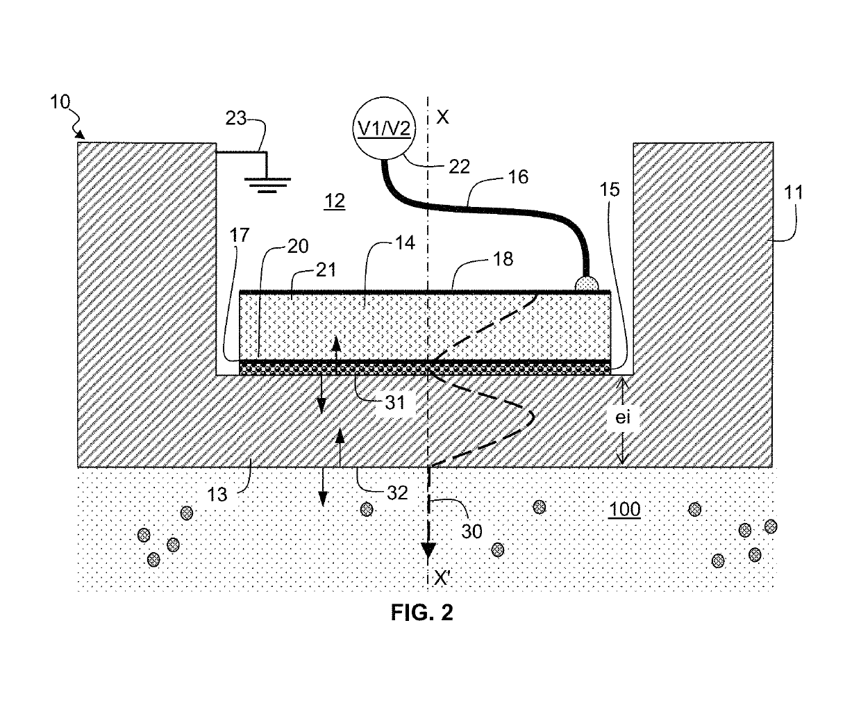
[0014]a back side of the piezoelectric element is arranged to be free to oscillate in the internal cavity so as to generate a high acoustic impedance mismatch between the piezoelectric element and the internal cavity at the back side and to maximize acoustic transmission at the front side; and
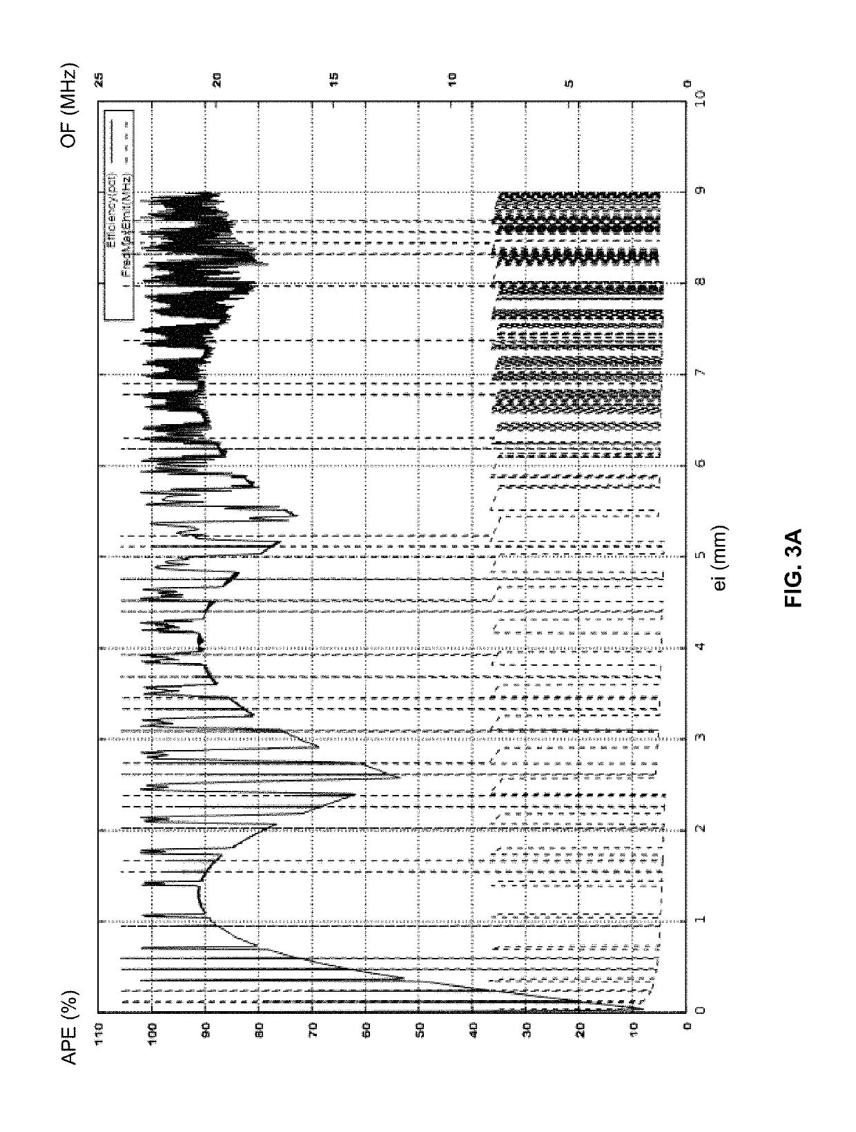
[0015]a thickness of the membrane wall is such that there is a common resonance between the membrane wall and the piezoelectric element thereby achieving high acoustic transmission through the membrane wall, and such that the membrane wall is suitable to resist to the downhole hydrocarbon well pressure.

Problems solved by technology

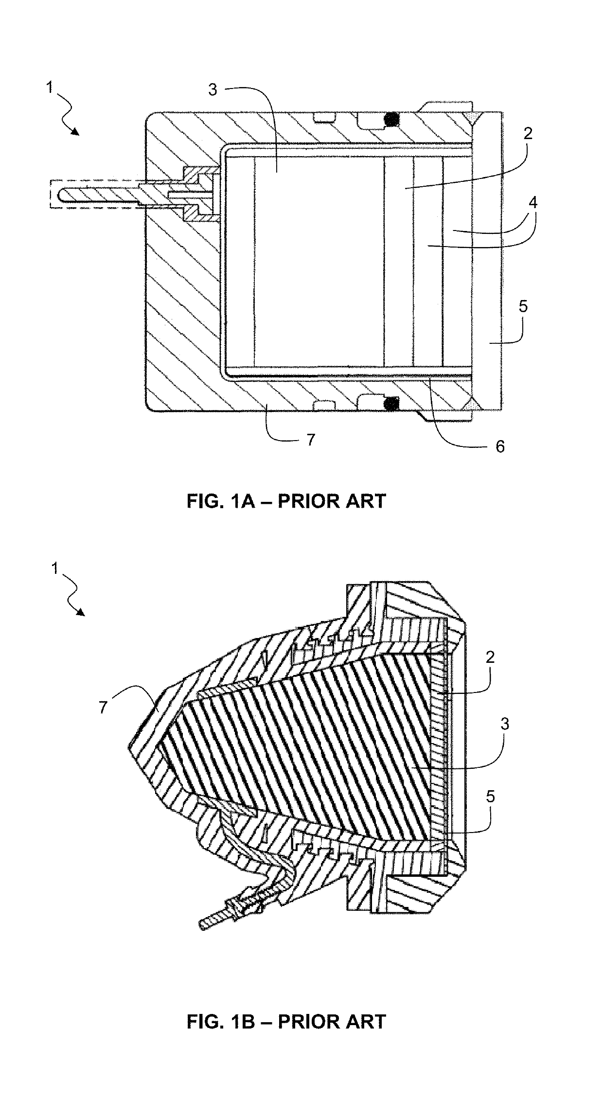
Ultrasonic transducer design is complex because material properties, structures geometries, assembly processes, as well as electrical connections, analog electronics front ends and digital computation algorithms have to be optimized in order to fit the specific requirements of the applications.
Such an ultrasonic transducer cannot be used in downhole environment where high pressure, high temperature and mechanical shocks would induce stresses resulting in damages to the piezoelectric element.
The drawbacks of such conventional solutions are their complex design using expensive and large mechanical pieces, hermetic electrical feedthrough to connect the transducer to electronic circuits which are positioned in part of the tool at atmospheric pressure, external membrane (e.g. of fluoroelastomer) to protect the piezo element against corrosive and conductive fluids, or complex pressure compensation arrangement to compensate for the pressure variations in the wellbore.

Method used


Image

  • Downhole acoustic transducer, downhole probe and tool comprising such a transducer
  • Downhole acoustic transducer, downhole probe and tool comprising such a transducer
  • Downhole acoustic transducer, downhole probe and tool comprising such a transducer

Examples


first embodiment

[0093]FIGS. 4 and 5 are a partial cross-section view and a perspective view, respectively, showing a downhole probe 40 including the downhole ultrasonic transducer 10 of FIG. 2. As an example, a plurality of such downhole ultrasonic probes 40 may be integrated into a production logging tool 60 that is depicted in perspective in FIG. 6.

[0094]The downhole probe 40 has the general shape of an elongated cylindrical body having a tip portion 41 in contact with the external environment 100 to be analyzed (i.e. in contact with harsh environments), and a second portion 42 separated by a housing element (partly visible in FIG. 6) from the external environment 100. A probe connector 43 separates the tip portion 41 from the second portion 42. The tip portion 41 comprises a downhole acoustic transducer 10 connected to the wire 25 and a protective tube 44 surrounding the wire 25. The protective tube 44 partially surrounds the downhole acoustic transducer 10, leaving at least the distal part (at ...

second embodiment

[0096]FIGS. 7, 8A and 8B are perspective front view, back view and A-A cross-section view, respectively, showing a downhole ultrasonic probe 50 including an angularly distributed array of downhole ultrasonic transducers 10. As an example, this downhole ultrasonic probe 50 may be integrated into a production logging tool 60 that is depicted in perspective in FIG. 9.

[0097]In this embodiment of downhole ultrasonic probe 50, the housing 51 forms an integral part of the body of the downhole tool 60. The housing 51 comprises three sections, a first cylindrical section 52, a second conical-like multifaceted section 53 and a third cylindrical section 54.

[0098]As better seen in the back view of FIG. 8A and A-A cross-section view of FIG. 8B, the first cylindrical section 52 is tube shaped and defines the internal cavity 12. Multiple blind holes forming sub-cavities 12A have been machined around the internal periphery of the internal cavity 12. The sub-cavities 12A are directed perpendicularly...

third embodiment

[0101]FIG. 10 shows a cross-section (top) and enlarged partial cross-section (bottom) views, respectively, illustrating a downhole ultrasonic probe 70 including an array of downhole ultrasonic transducers 10. FIG. 11 is a perspective view of an assembled downhole ultrasonic probe 70.

[0102]In this embodiment of downhole ultrasonic probe 70, the body of the downhole ultrasonic probe 70 comprises three sections 72, 73 and 74. The first section 72 is coupled to the second section 73 that is further coupled to the third section 74, these sections being assembled together (e.g. by welding). The first section 72 is a connector section having a tube shape and comprising a connector feedthrough 75 and a plug 76. The second section 73 comprises the array of downhole ultrasonic transducers 10, a printed circuit board 24 (e.g. including a control circuit, a processing circuit, etc. . . . ), a terminal board 77, the internal cavity 12 and multiple blind holes forming sub-cavities 12A receiving t...


PUM


Abstract

A downhole ultrasonic transducer (10) used to transmit and / or receive ultrasonic waves in a hydrocarbon well where a fluid is present comprises:a metal housing (11) defining an internal cavity (12) isolated from the fluid of the hydrocarbon well (100) by a membrane wall (13) made of metal or metal alloy;a piezoelectric element (14) mounted inside the internal cavity (12), the piezoelectric element (14) having a front side (20) mechanically coupled on the membrane wall (13);wherein:the internal cavity (12) is at a pressure unrelated to a hydrocarbon well pressure;a back side (21) of the piezoelectric element (14) is arranged to be free to oscillate in the internal cavity (12) so as to generate a high acoustic impedance mismatch between the piezoelectric element (14) and the internal cavity (12) at the back side (21) and to maximize acoustic transmission at the front side (20); anda thickness (ei) of the membrane wall (13) is such that there is a common resonance between the membrane wall and the piezoelectric element thereby achieving high acoustic transmission through the membrane wall (13), and such that the membrane wall (13) is suitable to resist to the hydrocarbon well pressure.

Description

TECHNICAL FIELD[0001]The invention relates to a downhole ultrasonic transducer, a downhole probe and a downhole tool comprising such a downhole ultrasonic transducer. The invention is particularly applicable to the performance of acoustic measurements at downhole pressure and temperature conditions. These measurements may be related to a borehole of a hydrocarbon well drilled into a subterranean formation (e.g. contactless caliper for measurement of the borehole diameter, borehole shape, casing corrosion, etc. . . . ), or to fluid flowing into such borehole (e.g. mud used in drilling operations, multiphase fluid mixtures flowing from a hydrocarbon bearing zone, etc. . . . ). The invention is particularly applicable in harsh downhole environment including high temperature (up to 200° C.), high pressure (up to 2.000 bars) and corrosive fluid.BACKGROUND[0002]Ultrasonic transducer design is complex because material properties, structures geometries, assembly processes, as well as electr...

Claims


Application Information

Patent Timeline
Patent Type & Authority Patents(United States)
IPC IPC(8): E21B47/08E21B17/10G06F17/50
CPCE21B17/1078G06F17/5009E21B47/082G01V2001/526B06B1/0674B06B3/00G01V1/159G01V1/52G06F30/20E21B47/085
Inventor DONZIER, ERICABBASSI, LINDATAVERNIER, EMMANUEL
Owner OPENFIELD
Learn More