Ventilation flap assembly for a vehicle

a technology for ventilating flaps and vehicles, applied in the direction of radiators, vehicle safety arrangments, component optimization, etc., can solve the problems of high energy consumption, high construction cost of ventilating flap assemblies, and many movable parts

Active Publication Date: 2019-11-12
WEIDPLAS
View PDF92 Cites 0 Cited by
  • Summary
  • Abstract
  • Description
  • Claims
  • Application Information

AI Technical Summary

Benefits of technology

[0010]It is, therefore, an object of the present invention to specify a structurally simple ventilation flap assembly for a vehicle in which the ventilation flaps may be adjusted using a small expenditure of force.

Problems solved by technology

However, this ventilation flap assembly has a relatively complicated construction with many movable parts.
For adjusting the ventilation flaps, therefore, relatively powerful drive devices have to be used, said drive devices being accordingly costly, having a high energy consumption and requiring considerable space.
Such a ventilation flap control for a plurality of air inlet openings which only uses a single drive device, however, is only suitable for specific situations and when the different air inlet openings are arranged in the vicinity of one another.
Moreover, this ventilation flap assembly has a relatively complex design with many components movably connected together.
Accordingly, the mounting of this ventilation flap assembly is complicated.

Method used


Image

  • Ventilation flap assembly for a vehicle
  • Ventilation flap assembly for a vehicle
  • Ventilation flap assembly for a vehicle

Examples


first embodiment

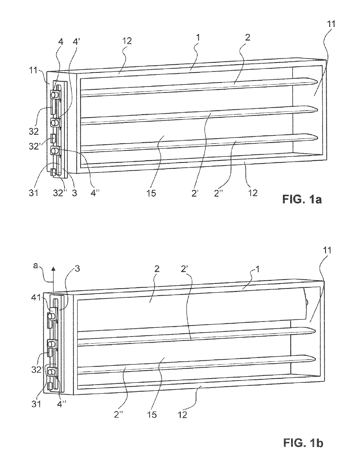
[0036]FIG. 1a shows a perspective view of a ventilation flap assembly according to the invention, wherein the actuating element adopts a basic position;

[0037]FIG. 1b shows a perspective view of the ventilation flap assembly of FIG. 1a, wherein the actuating element adopts a first intermediate position;

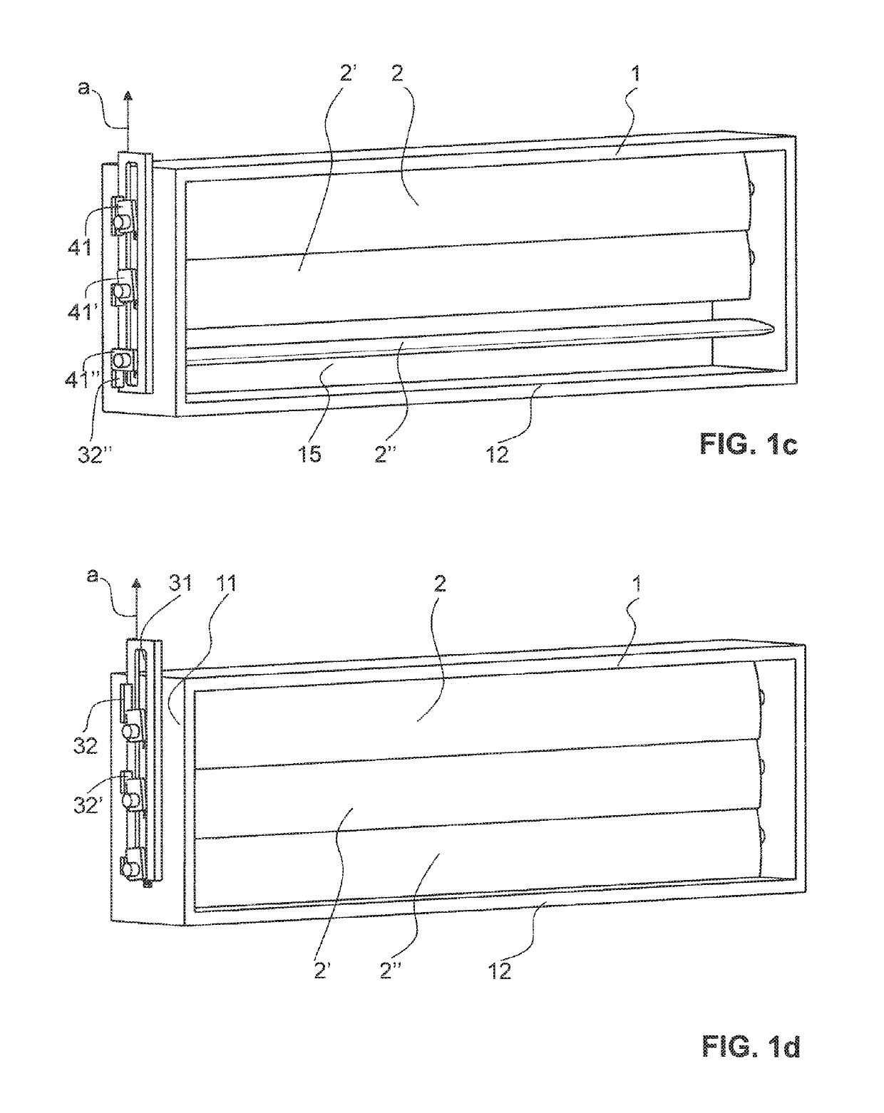
[0038]FIG. 1c shows a perspective view of the ventilation flap assembly of FIG. 1a, wherein the actuating element adopts a second intermediate position,

[0039]FIG. 1d shows a perspective view of the ventilation flap assembly of FIG. 1a, wherein the actuating element adopts an end position;

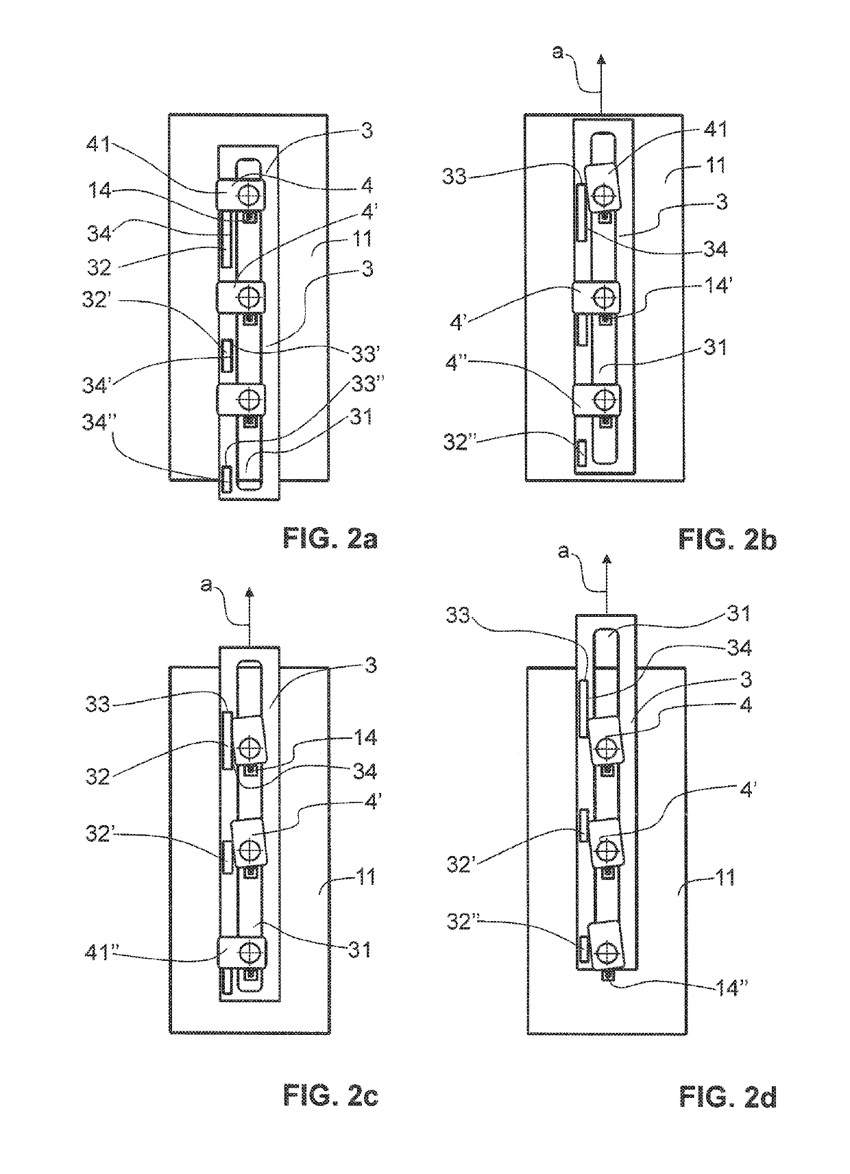
[0040]FIG. 2a shows a side view of the ventilation flap assembly shown in FIG. 1a;

[0041]FIG. 2b shows a side view of the ventilation flap assembly shown in FIG. 1b;

[0042]FIG. 2c shows a side view of the ventilation flap assembly shown in FIG. 1c;

[0043]FIG. 2d shows a side view of the ventilation flap assembly shown in FIG. 1d;

[0044]FIG. 3 shows an exploded view of the ventilation flap assembly sho...

second embodiment

[0049]FIG. 8 shows a side view of a ventilation flap assembly according to the invention with an integrated drive unit;

third embodiment

[0050]FIG. 9 shows a side view of a ventilation flap assembly according to the invention with an integrated drive unit;


PUM


Abstract

Disclosed is a ventilation flap assembly for a vehicle, in particular a motor vehicle (8), the assembly having at least one first and one second ventilation flap (2, 2′) in addition to an actuating element (3). Each of the first and the second ventilation flaps (2, 2′) can be moved from a first position into a second position, in order to allow the passage of a quantity of air, which differs in the second position in comparison to the quantity of air in the first position, through an air opening (83, 84) of the vehicle. The actuating element (3) is used to move both the first and the second ventilation flaps (2, 2′) and said actuating element (3) is designed, when actuated, to firstly move the first ventilation flap (2) from its first position into its second position and only then to move the second ventilation flap (2′) from its first position into its second position.

Description

CROSS REFERENCE TO RELATED APPLICATIONS[0001]This application is a National Stage of International Application No. PCT / EP2016 / 067749, filed on Jul. 26, 2016, which claims priority from European Patent Application No. 15179308.0, filed on Jul. 31, 2015, the contents of all of which are incorporated herein by reference in their entirety.TECHNICAL FIELD[0002]The present invention relates to a ventilation flap assembly for a vehicle, in particular a motor vehicle. The ventilation flap assembly serves for controlling the quantity of air from incoming and / or outgoing air through an air opening of the vehicle.PRIOR ART[0003]Vehicles and, in particular, motor vehicles, such as for example automobiles, generally have a plurality of air inlet openings and air outlet openings in order to conduct waste air from an interior of the vehicle to the outside or in order to introduce fresh air from outside the vehicle into the interior. An air supply opening may serve, for example, for cooling the eng...

Claims


Application Information

Patent Timeline
Patent Type & Authority Patents(United States)
IPC IPC(8): B60K11/08B60R19/52
CPCB60R19/52B60K11/085Y02T10/88B60R2019/525
Inventor LAMBERT, SVEN
Owner WEIDPLAS
Why Eureka
Try Eureka