
Staple formation detection mechanisms

Active Publication Date: 2019-10-29
CILAG GMBH INT
View PDF6994 Cites 690 Cited by
  • Summary
  • Abstract
  • Description
  • Claims
  • Application Information

AI Technical Summary

Problems solved by technology

Furthermore, most sensing systems rely on complicated sensors or induction in order to detect and assess the status of an end effector system.

Method used


Image

  • Staple formation detection mechanisms
  • Staple formation detection mechanisms
  • Staple formation detection mechanisms

Examples


Embodiment Construction

[0148]Applicant of the present application owns the following patent applications that were filed on Apr. 15, 2016 and which are each herein incorporated by reference in their respective entireties:

[0149]U.S. patent application Ser. No. 15 / 130,582, entitled SURGICAL INSTRUMENT WITH DETECTION SENSORS;

[0150]U.S. patent application Ser. No. 15 / 130,588, entitled SURGICAL INSTRUMENT WITH IMPROVED STOP / START CONTROL DURING A FIRING MOTION;

[0151]U.S. patent application Ser. No. 15 / 130,595, entitled SURGICAL INSTRUMENT WITH ADJUSTABLE STOP / START CONTROL DURING A FIRING MOTION;

[0152]U.S. patent application Ser. No. 15 / 130,566, entitled SURGICAL INSTRUMENT WITH MULTIPLE PROGRAM RESPONSES DURING A FIRING MOTION;

[0153]U.S. patent application Ser. No. 15 / 130,571, entitled SURGICAL INSTRUMENT WITH MULTIPLE PROGRAM RESPONSES DURING A FIRING MOTION;

[0154]U.S. patent application Ser. No. 15 / 130,581, entitled MODULAR SURGICAL INSTRUMENT WITH CONFIGURABLE OPERATING MODE;

[0155]U.S. patent application S...


PUM


Abstract

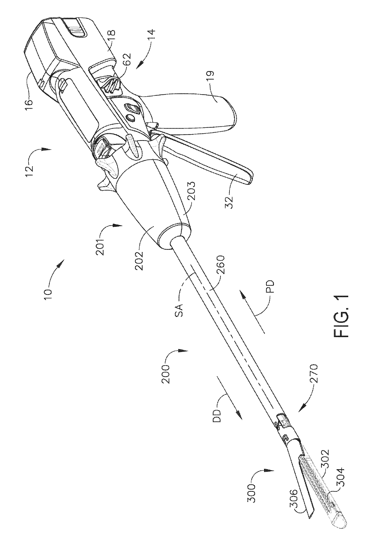
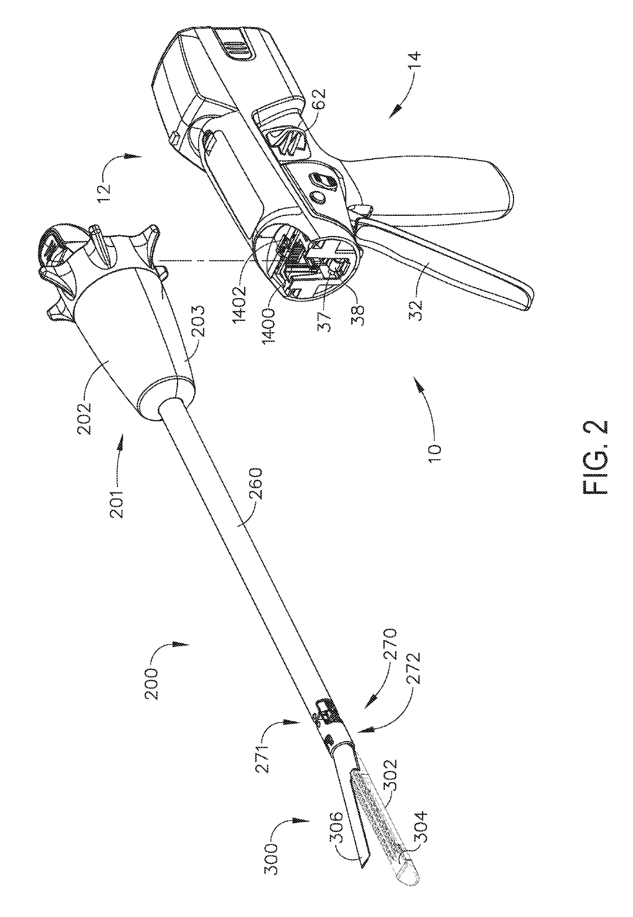
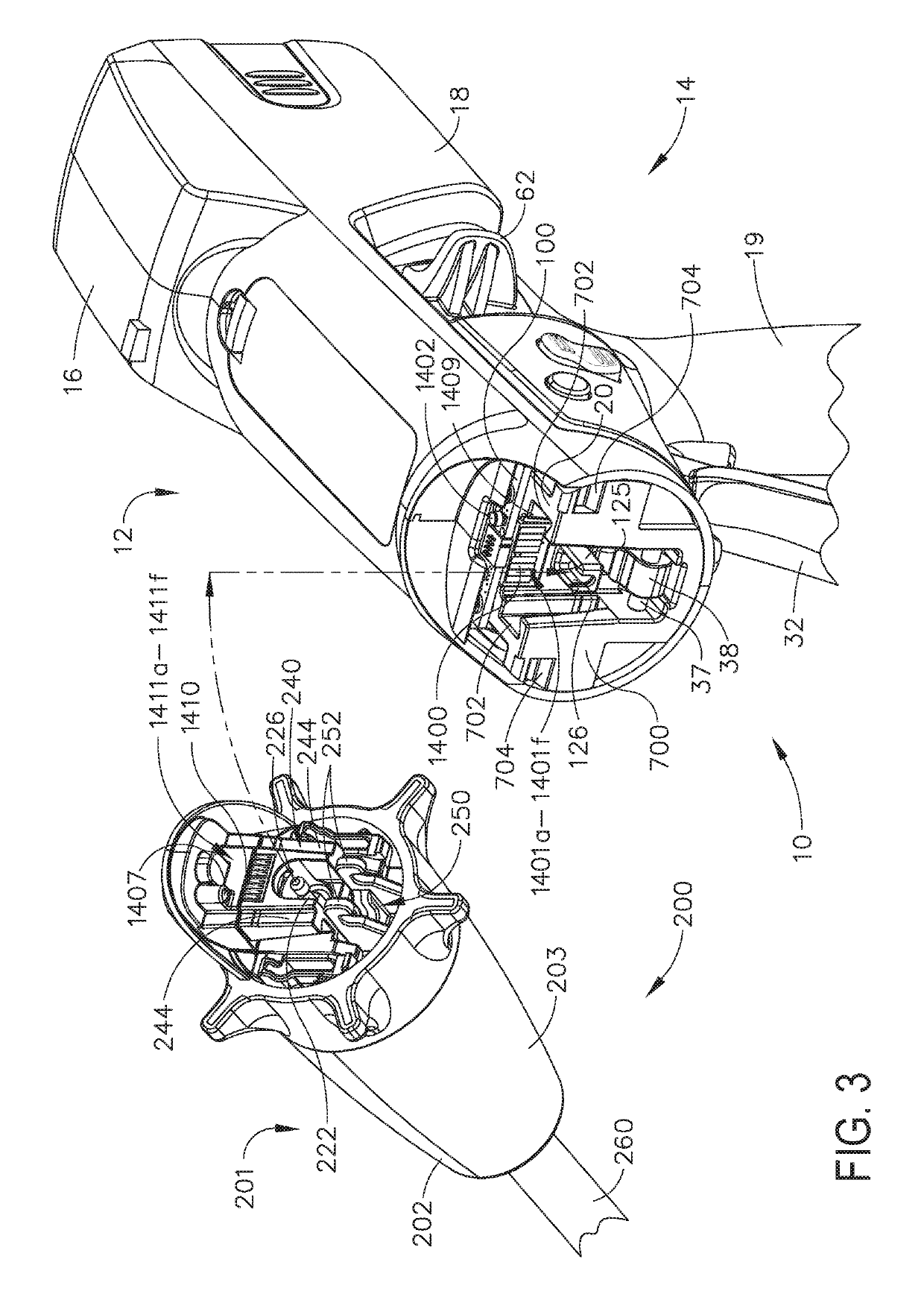
A medical instrument has an elongated channel configured to support a staple cartridge, the staple cartridge comprising a plurality of staples. The medical instrument also has an anvil mechanically coupled to the elongated channel, wherein the anvil comprises an exterior surface extending between a proximal end and a distal end. In addition, the medical instrument has at least one electrical circuit at least partially positioned on the exterior surface of the anvil, an indicator system comprising at least one indicator, and a logic circuit electrically in electrical communication with the at least one electrical circuit and the indicator system, wherein the logic circuit is configured to activate the at least one indicator when an electrical continuity of the at least one electrical circuit is interrupted.

Description

TECHNICAL FIELD[0001]The present disclosure relates to surgical instruments and, in various circumstances, to surgical stapling and cutting instruments and staple cartridges therefore that are designed to staple and cut tissue.BACKGROUND[0002]In a motorized surgical stapling and cutting instrument, it would be helpful to record when the cartridge has fired and potentially lockout spent cartridges via an electrical means. Further, it would be helpful to detect contact of a staple leg when it is positioned outside the intended pocket contact zone on an anvil. Similarly, it would be helpful to detect the formation of a staple employing anvil pocket contacts. In addition, it would be helpful to detect contact of a predetermined number of staple tip contacts with anvil pockets as well as the predetermined sequencing of the staple contacts. Moreover, it would be helpful to sense the presence of the DLU, removable channel, loaded status of the cartridge, proper seating of the cartridge, an...

Claims


Application Information

Patent Timeline
Patent Type & Authority Patents(United States)
IPC IPC(8): A61B17/072A61B17/068A61B17/10A61B90/00A61B90/30A61B17/29A61B17/00A61B90/98
CPCA61B17/105A61B17/07207A61B17/068A61B2017/00026A61B2017/0046A61B2017/0023A61B2090/309A61B90/98A61B2017/00057A61B2017/00017A61B2017/00734A61B2017/2927A61B2017/00398A61B2090/065A61B2017/07271A61B2017/07257A61B2017/07278A61B2090/0807A61B2017/00473A61B2017/00123A61B2017/00929A61B2017/00725A61B2017/00415A61B2017/07285A61B2017/00119A61B2017/07264A61B2017/00066
Inventor VENDELY, MICHAEL J.SCHEIB, CHARLES J.SHELTON, IV, FREDERICK E.HARRIS, JASON L.MOIR, ROBERT S.CONSONNI, SOFIA MARIASAMS, STEPHENAKRAM, ISMAILGOLDREIN, HOWELL T.
Owner CILAG GMBH INT
Learn More