Method for pressure control in a supply network, device and supply network

a technology of supply network and pressure control, applied in the direction of computer control, program control, instruments, etc., can solve the problems of high repair cost, water loss, premature aging and failure of components, etc., and achieve the effect of simple analysis, low complexity and fast execution

Active Publication Date: 2019-10-15
SIEMENS AG
View PDF25 Cites 1 Cited by
  • Summary
  • Abstract
  • Description
  • Claims
  • Application Information

AI Technical Summary

Benefits of technology

[0010]In other words, a simulation model of the supply network is therefore created. The simulation model simulates pressure and / or flow profiles in a manner dependent on consumption profiles. The data describing the pressure and / or flow profiles are subsequently reduced. All of this can take place “offline”, i.e. away from the actual operation, in particular prior to putting the supply network into operation. In an “online” part of the method, i.e. during the operation of the supply network, a first pressure and / or flow value now is measured at at least one first point in the supply network by means of at least one first sensor. However, in order now to determine a second pressure and / or flow value at at least one second point in the supply network as well, the latter is reconstructed from the reduced data and using the at least one first pressure and / or flow value. In very general terms, the reduced data contain less data and / or have a lower data complexity than the (non-reduced) data. Using the reduced data for determining the second pressure and / or flow values is advantageous in that less computational power is required and, accordingly, a quick actuation of the at least one pump or of the at least one valve is made possible, in particular in real time. “Reconstructing” should be understood to mean that the at least one second pressure and / or flow value was contained or approximately contained in the (non-reduced) data and there is a back calculation to this at least one second pressure and / or flow value on the basis of the reduced data with the aid of the at least one first pressure and / or flow value.
[0028]In accordance with a further embodiment, a minimum pressure is established from the at least one first pressure value and the at least one second pressure value. The at least one pump and / or the at least one valve is / are actuated in a manner dependent on the difference between an intended value and the established minimum pressure. The intended pressure value for example corresponds to a minimum pressure prescribed by law. Accordingly, the at least one pump and / or the at least one valve is therefore actuated in such a way that the pressure lies below the intended pressure value at no point within the supply network. However, at the same time, such a control is sought after that the minimum pressure in the entire supply network equals the intended pressure value or is only slightly thereabove. As a result, the network components in the supply network can be spared.

Problems solved by technology

On the other hand, excessively high pressure in the supply network leads to premature aging and failure of components, for example by pipes breaking.
The leaks caused thereby lead to high repair costs, water losses and, in some cases, to further damage of surrounding structures.
Moreover, excessive pressure leads to an increased water loss as a result of background leaks.
Such background leaks are present in every water network to a certain extent and have as a consequence a continuous loss of drinking water.
Moreover, an excessive flow pressure increases the frictional losses occurring in the case of pipe flows.
In supply networks in which the pressure is built up by pumps, an increase in the provided pressure immediately leads to an increased energy requirement of the pumps.
Operators of supply networks are therefore presented with the challenge of finding a compromise between these two opposing requirements in respect of the hydraulic pressure provided in the supply network.
This decision is additionally made more difficult by virtue of the pressure prevalent during operation being strongly influenced by the consumption load, which may be exposed to large variations and often cannot be reliably measured or predicted.
These consumption variations and switching processes of pumps and valves can furthermore lead to transient pressure peaks in the supply network, which can have a damaging effect on network components and often constitute the cause of suddenly occurring leaks.
The design of the network components is already deliberately over-scaled during planning.
The disadvantages, listed above, as a result of the long-term operation at a high pressure are often accepted.

Method used


Image

  • Method for pressure control in a supply network, device and supply network
  • Method for pressure control in a supply network, device and supply network
  • Method for pressure control in a supply network, device and supply network

Examples


Embodiment Construction

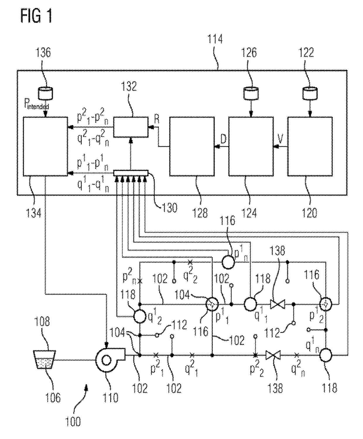
[0045]FIG. 1 shows a supply network 100. By way of example, the shown supply network 100 is a so-called DMA (district metering area) in a larger, superordinate supply network which, incidentally, is not depicted.

[0046]By way of example, the supply network 100 is a water supply network and it is composed of pipes or lines 102, which merge at nodes 104. Via the pipes 102 and nodes 104, water 106 from a store 108 is distributed to consumers 112 by way of a pump 110. In addition to the pump 110, provision could also be made of a valve (not depicted here), which controls a water flow through the supply network 100.

[0047]Furthermore, provision is made of a device 114, which actuates the pump 110, in particular an electric motor of same, in order thus to adjust a pressure which the pump 110 applies to the water. The pump 110 or the motor thereof can have a variable rotational speed, with the rotational speed being controlled by the device 114. The device 114 is signal-connected to pressure...


PUM


Abstract

A supply network for supplying consumers with a medium is provided. Based on a reduction of data and a subsequent reconstruction of at least one pressure and / or flow value, the state at least at one further location in the supply network can be determined without having to be measured. An improved actuation of the at least one pump and / or of the at least one valve is thus possible. A device for pressure control in a supply network is also provided.

Description

CROSS-REFERENCE TO RELATED APPLICATIONS[0001]This application claims priority to PCT Application No. PCT / EP2015 / 050668, having a filing date of Jan. 15, 2015, based off of German application No. DE 102014205332.3 having a filing date of Mar. 21, 2014, the entire contents of which are hereby incorporated by reference.FIELD OF TECHNOLOGY[0002]The following relates to a method for pressure control in a supply network for supplying consumers with a medium. Furthermore, embodiments of the present invention relate to a device for pressure control in a supply network and to a supply network. Even though embodiments of the present invention are described below with reference to water supply networks, it is equally applicable to other supply networks, such as e.g. gas networks or district heating networks.BACKGROUND[0003]The hydraulic pressure prevalent in a water supply network is an important quality feature. A high pressure guarantees that a large amount of water can be taken from the sup...

Claims


Application Information

Patent Timeline
Patent Type & Authority Patents(United States)
IPC IPC(8): E03B7/02G06F17/18G05B19/042G05B17/02
CPCG05B19/042E03B7/02G05B17/02G06F17/18
Inventor ALLMARAS, MORITZWEHRSTEDT, JAN CHRISTOPHWEVER, UTZ
Owner SIEMENS AG
Why Eureka
Try Eureka