
Modular sections for temporary turntable applications

a technology of modular sections and turntables, applied in the field of turntables, can solve the problems of inability to easily spread out the cost among other projects and other customers, the turntable can be very expensive, so as to achieve easy and cost-efficient adjustment, the effect of easy and cost-efficien

Active Publication Date: 2019-10-01
MACTON CORP +1
View PDF39 Cites 0 Cited by
  • Summary
  • Abstract
  • Description
  • Claims
  • Application Information

AI Technical Summary

Benefits of technology

The invention is a turntable that can be easily modified in size and capacity to meet different customer needs. It is designed with modular sections that can be added or removed from a base version of the turntable to adjust its size and capacity. These modular sections can be quickly and easily replaced with sections of different strengths or with different hole patterns for easy attachment. The turntable can also have additional or reduced wheel-sets, track sections, and drive units to allow for easy movement around its axis of rotation. Overall, this design allows for flexibility and efficiency in accommodating various customer needs.

Problems solved by technology

Once the cable has been laid underwater for that particular project, the turntable often has no other uses unless there is another project that requires a turntable having a similar diameter and loading capacity, which is not very often, resulting typically in the immediate obsolescence of that turntable.
For customers needing to purchase a turntable for one of these projects, the turntable can be very expensive (since it is often large and made out of steel to accommodate very large loads) and its cost cannot be easily spread out amongst other projects and other customer uses if those other projects and customer uses require different turntable sizes or load capacities.
For some customers, they have attempted to address this problem by having an existing turntable be modified after its initial use to accommodate another project by hiring one or more other firms to develop a design for the different sizes and load capacities needed and then to manufacture and ship the parts needed for such modifications, and to extensively cut up and modify the existing turntable for such modifications (which can be very expensive and time-consuming).
In some cases, the modified turntable may not work as well as a turntable that was designed and built from scratch, since the modifications may require extensive cutting, drilling, welding, grinding and fit-up work be done between new and old parts that may not mate up well with one another.

Method used


Image

  • Modular sections for temporary turntable applications
  • Modular sections for temporary turntable applications
  • Modular sections for temporary turntable applications

Examples


Embodiment Construction

[0030]Referring now to the drawings, wherein like reference numerals designate corresponding structure throughout the views. The following examples are presented to further illustrate and explain the present invention and should not be taken as limiting in any regard.

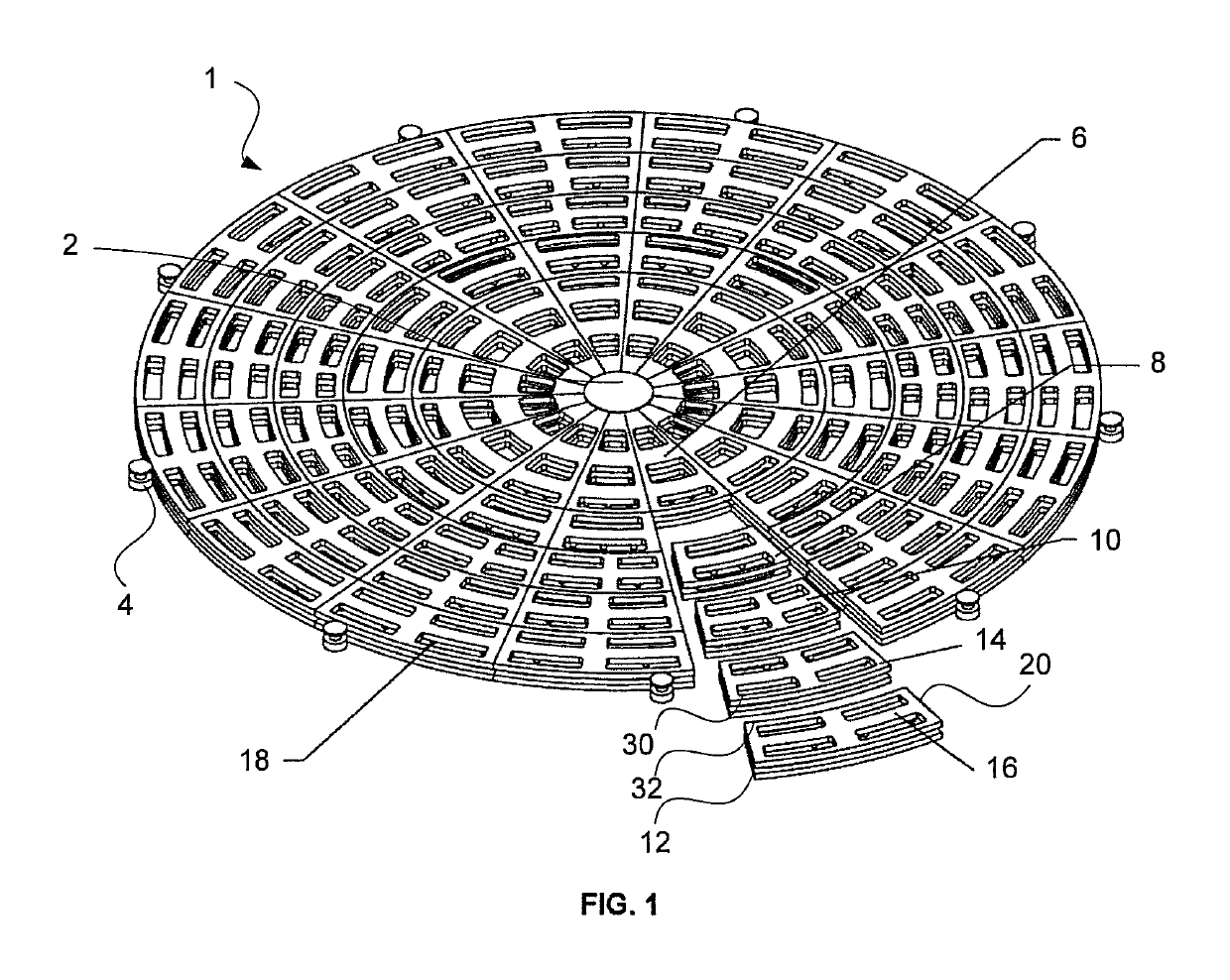
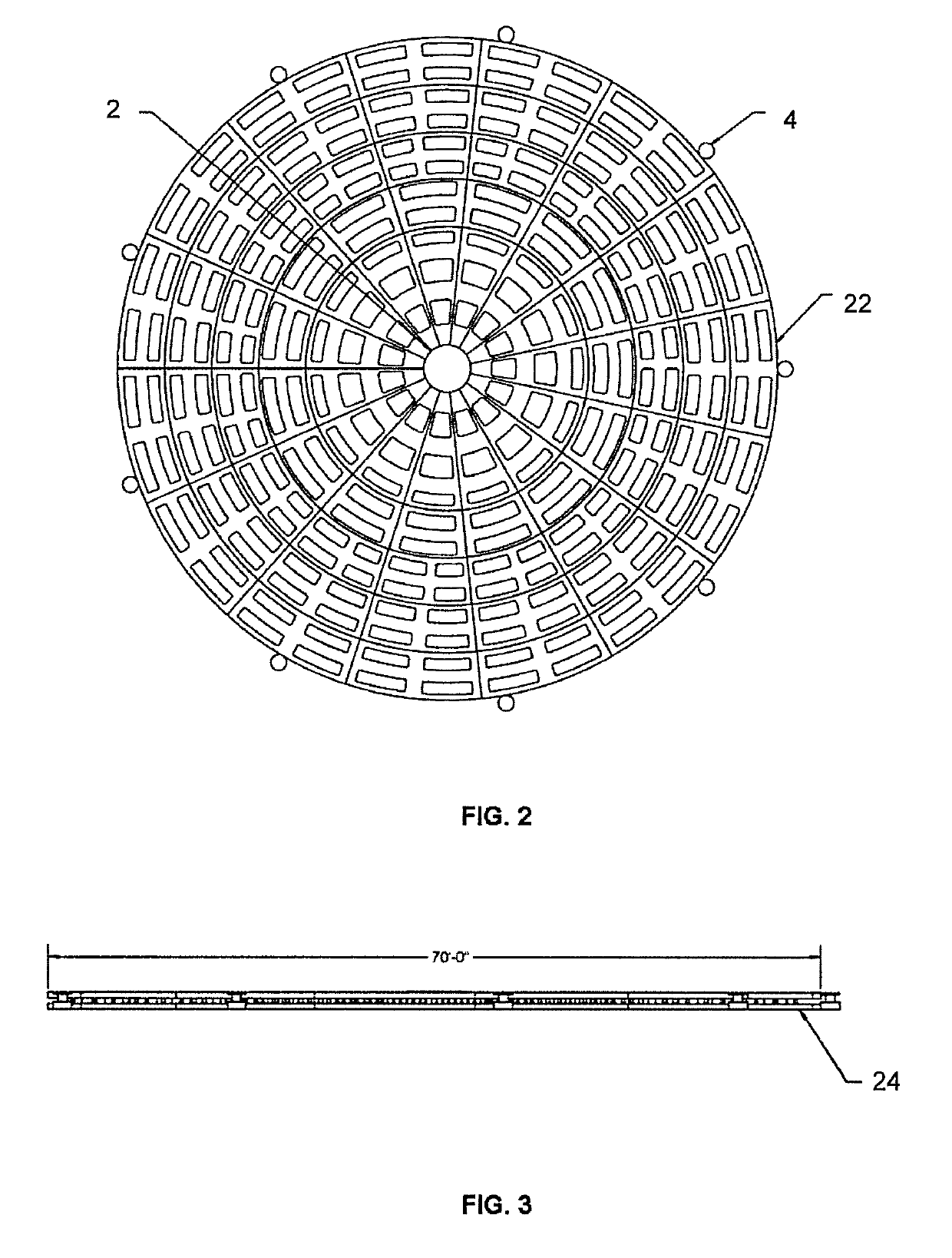
[0031]In FIGS. 1-3, turntable 1 is shown partially assembled with four concentric rings having a number of modular sections. The first ring has sections that correspond to modular section 8, the second ring to modular section 10, the third ring to modular section 14 and the fourth ring to modular section 16. These rings surround center ring that is made up of modular sections that correspond to modular section 6. A hub 2 that defines the axis of rotation of the turntable (extending out of the page at the center in FIG. 2). The center ring is attached to this hub 2 so that the turntable can rotate. The modular sections (i.e. 6, 8, 10, 14, 16) all include rolling supports 18 that are sandwiched between parts of the modula...


PUM


Abstract

A turntable in modular pie or other sections, which sections can be added or taken away in concentric rings from a base version of the turntable in order to scale the size and capacity of that turntable to accommodate a wide range of size and loading needs.

Description

FIELD OF THE INVENTION[0001]The present invention relates to a turntable. More specifically, the invention relates to a modular turntable for temporary customer uses (such as turntables temporarily affixed to the deck of a ship that are used for the laying of underwater cables), that can be increased or reduced in size to fit the customer's needs on a particular project.BACKGROUND OF THE INVENTION[0002]Prior art turntables are generally fixed in size for a particular application, so they are specifically designed and manufactured for just one set of customer needs (i.e., built to a specific turntable diameter and with one or more specific loading capacities). For instance, when underwater power or signal cables need to be laid underwater for the transmission of electric power or communications signals from one ocean or lake coast to another, it is often done by the mounting of turntables that contain such cables onto the deck of a ship or barge and then as the ship or barge leaves o...

Claims


Application Information

Patent Timeline
Patent Type & Authority Patents(United States)
IPC IPC(8): B65H49/28B65H75/30
CPCB65H75/30B65H49/28B65H2701/34B65H49/24
Inventor MCGONAGLE, PETERSCHUMACHER, STEPHEN
Owner MACTON CORP
Learn More