Arched steel fibers for reinforcing cement-based material
a cement-based material and steel fiber technology, applied in the direction of transportation and packaging, structural elements, building components, etc., can solve the problems of weak limits under tensile or dynamic loading, low impact strength, energy absorption capacity, etc., to achieve significant reduction of pullout resistance strength, improve mechanical performance such as tensile strength, flexural strength, energy absorption capability, and the like. , the effect of improving the strength of the strength
- Summary
- Abstract
- Description
- Claims
- Application Information
AI Technical Summary
Benefits of technology
Problems solved by technology
Method used
Image
Examples
exemplary embodiment 1
[0040]In order to determine adhesion performance of the arched steel fiber for the cement-based material according to the exemplary embodiment of the present invention, a pullout test was performed on the arched steel fiber for the cement-based material according to the exemplary embodiment of the present invention and conventional hook-type steel fiber for the cement-based material.
[0041]In order to perform the pullout test, a dog-bone-shaped mortar specimen was divided into two portions according to JCI SF-8, and then a steel fiber was embedded 25 mm into each center of the divided portions.
[0042]Compression strength of the mortar was 30 MPa, and steel fibers used in the pullout test each had a tensile strength of 1300 MPa, a diameter of 0.75 mm, and a length of 60 mm.
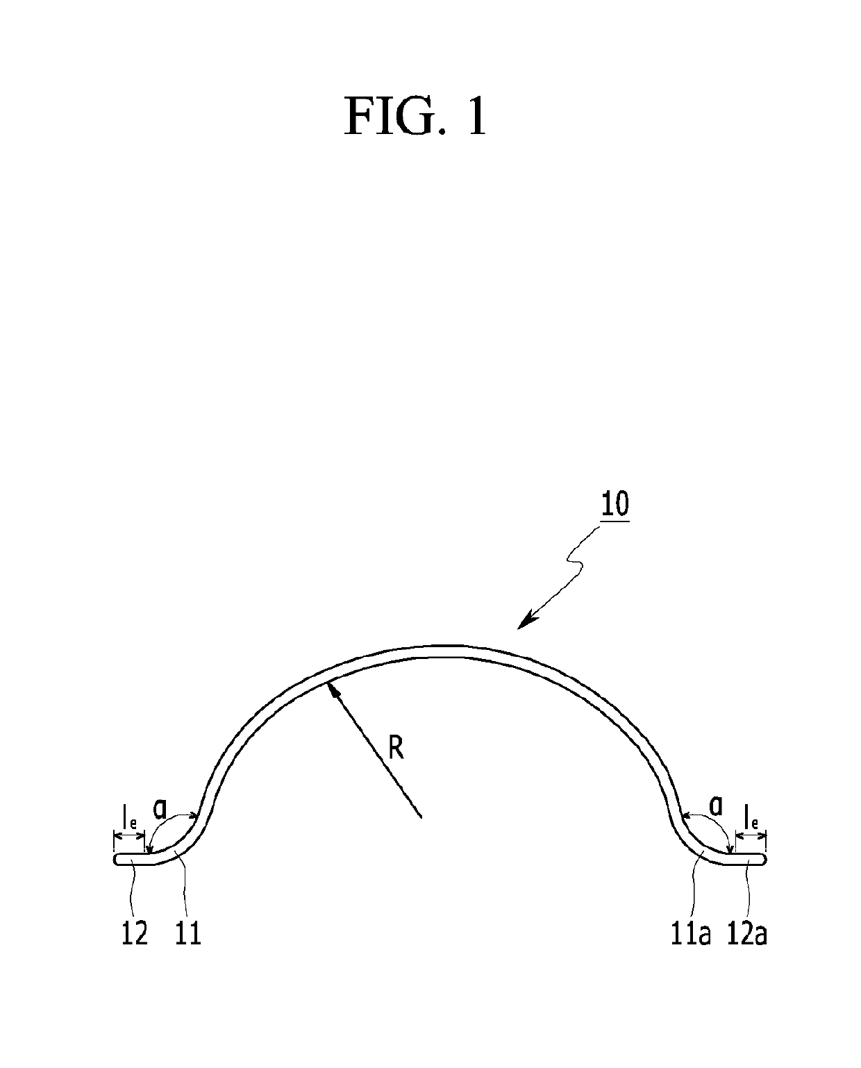
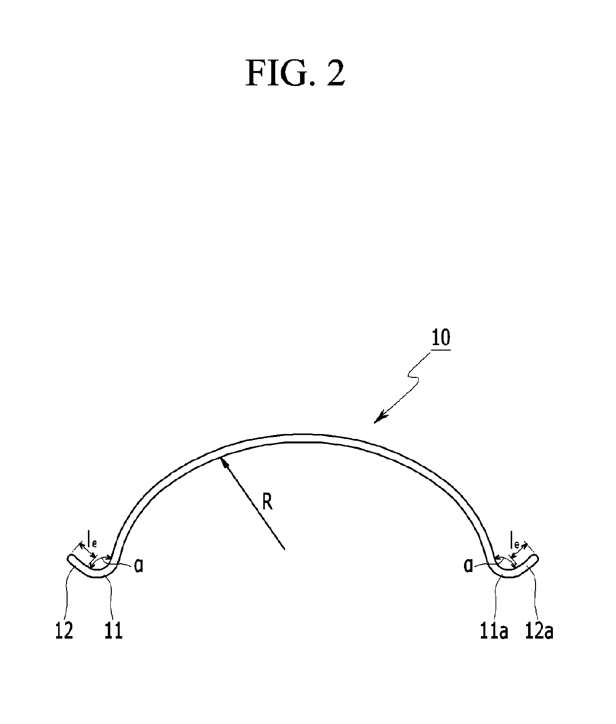
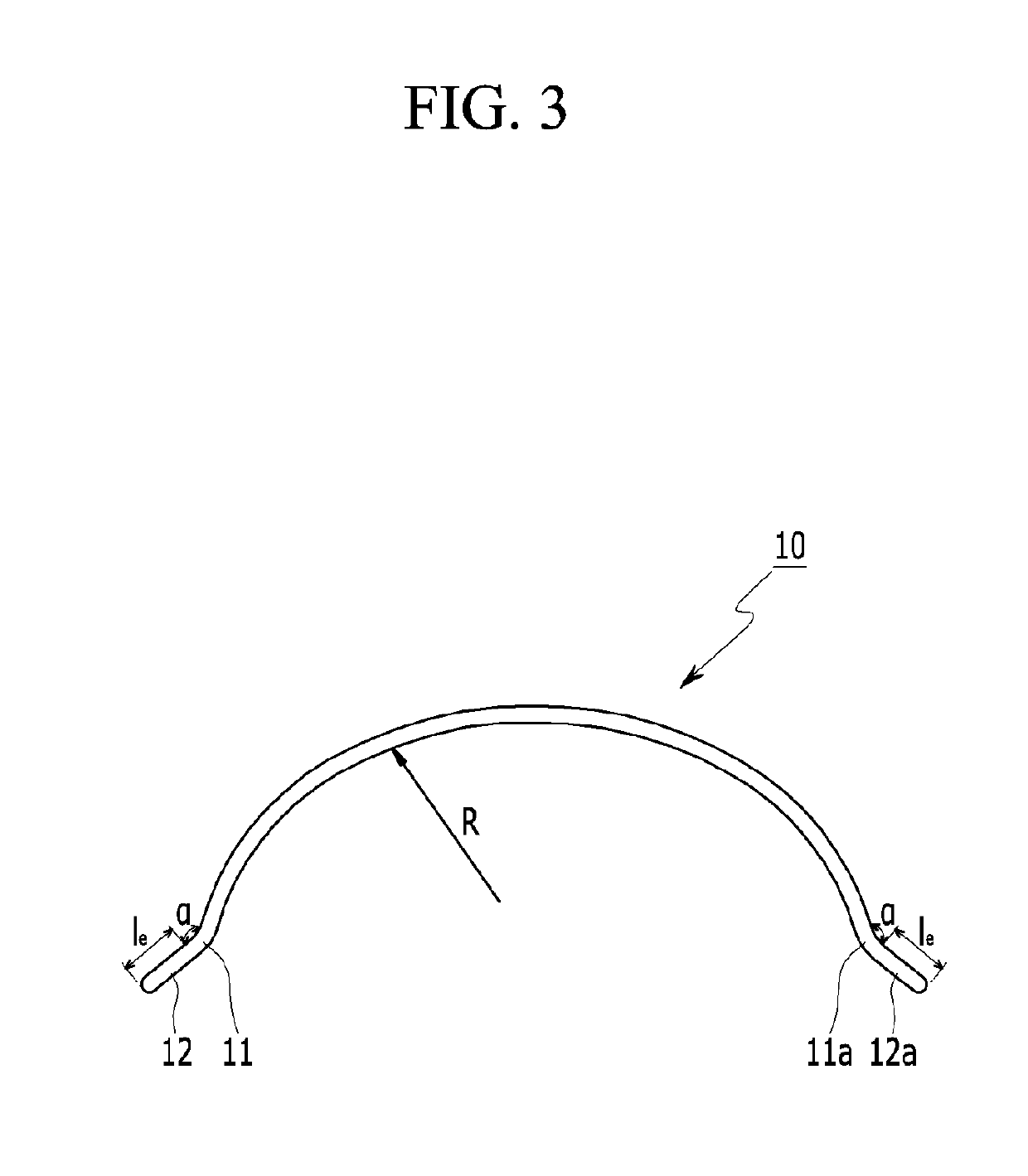
[0043]In manufacturing of the arched steel fiber for reinforcement of the cement-based material according to the exemplary embodiment of the present invention, a curvature radius R of the arch was set to 35 mm, the a...
exemplary embodiment 2
[0046]In order to determine adhesion performance according to the length le of the straight lines 12 and 12a of the arched steel fiber for reinforcement of the cement-based material according to the exemplary embodiment of the present invention, a pullout test was performed with the length le of the straight lines 12 and 12a as a variable.
[0047]A pullout test method, an embedment length, and a compression strength of mortar were set to be the same as those of Exemplary Embodiment 1, and steel fibers used in the pullout test were prepared with a tensile strength of 1300 MPa, a diameter of 0.75 mm, and a length of 60 mm. The lengths le of the straight ends 12 and 12a were respectively set to 0, 1.5 mm, 2.5 mm, and 3.5 mm.
[0048]As shown in the results of the pullout test, represented by the graph of FIG. 5, maximum pullout loads of the straight ends 12 and 12a were improved by 437%, 450%, and 575%, respectively, when the lengths le of the straight ends 12 and 12a were set to 1.5 mm, 2....
exemplary embodiment 3
[0049]In order to determine bending performance of concrete reinforced by the arched steel fiber according to the exemplary embodiment of the present invention, bending performance was tested on the arched steel fiber, the conventional hook-type steel fiber, and circular-shaped steel fiber.
[0050]A specimen used in the test was manufactured as a 150 mm×150 mm×550 mm specimen having a prismatic shape, and a third-point bending test was performed according to JSCE-SF4.
[0051]Table 1 shows a mixing ratio of concrete for determination of bending performance, and steel fiber that has the same specification as of the arched steel fiber of Exemplary Embodiment 1 for the pullout test and the hooked-type steel fiber were applied, and in the case of the circular-shaped steel fiber, the tensile strength was 1300 MPa, the diameter was 0.75 mm, and the interior diameter was 30 mm. A mixing amount was 30 kg / m2.
[0052]
TABLE 1Unit material amount (kg / m3)HighperformanceAEDesignCoarseAirwaterstandardagg...
PUM
| Property | Measurement | Unit |
|---|---|---|
| curvature radius | aaaaa | aaaaa |
| length | aaaaa | aaaaa |
| length | aaaaa | aaaaa |
Abstract
Description
Claims
Application Information
 - R&D
- Intellectual Property
- Life Sciences
- Materials
- Tech Scout
- Unparalleled Data Quality
- Higher Quality Content
- 60% Fewer Hallucinations
Browse by: Latest US Patents, China's latest patents, Technical Efficacy Thesaurus, Application Domain, Technology Topic, Popular Technical Reports.
© 2025 PatSnap. All rights reserved.Legal|Privacy policy|Modern Slavery Act Transparency Statement|Sitemap|About US| Contact US: help@patsnap.com


