Combined needle holder scissors
a technology of scissors and needle holders, applied in the field of multi-purpose medical devices, can solve the problems of unsuitable surgical applications, risky passing of devices in such a manner, undue difficulty in use, etc., and achieve the effect of safe use as a grasper
- Summary
- Abstract
- Description
- Claims
- Application Information
AI Technical Summary
Benefits of technology
Problems solved by technology
Method used
Image

Examples
first embodiment
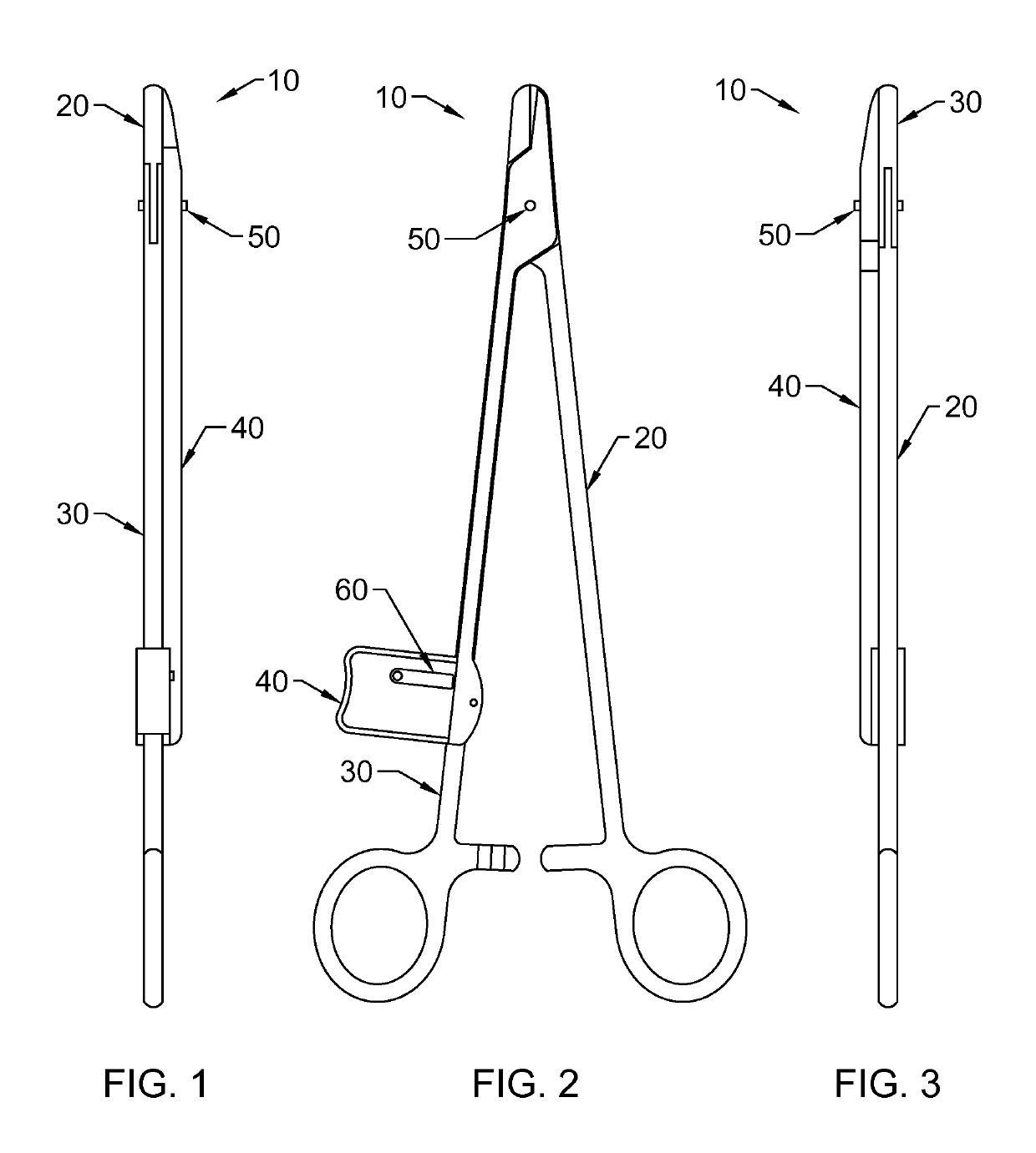
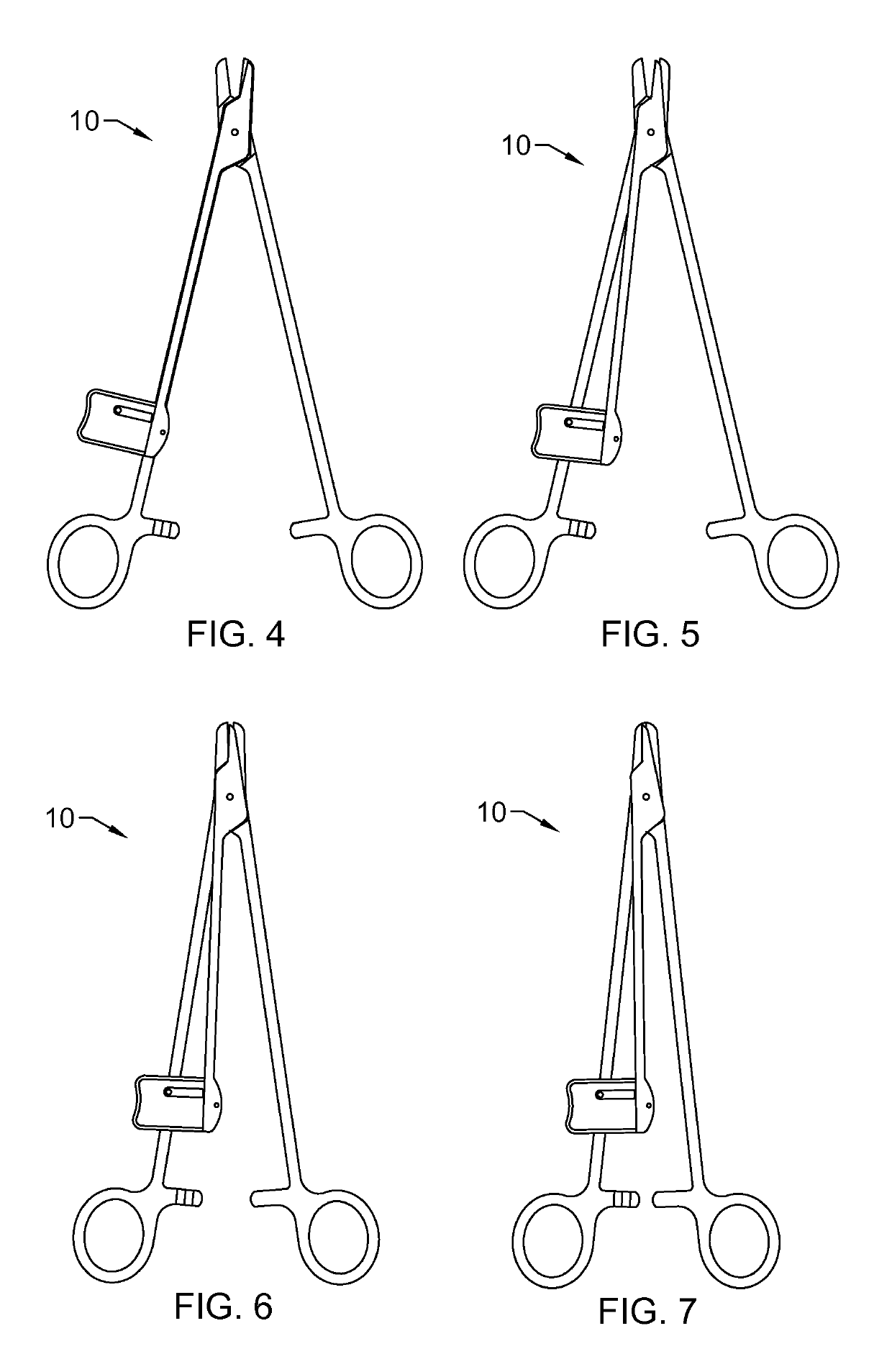
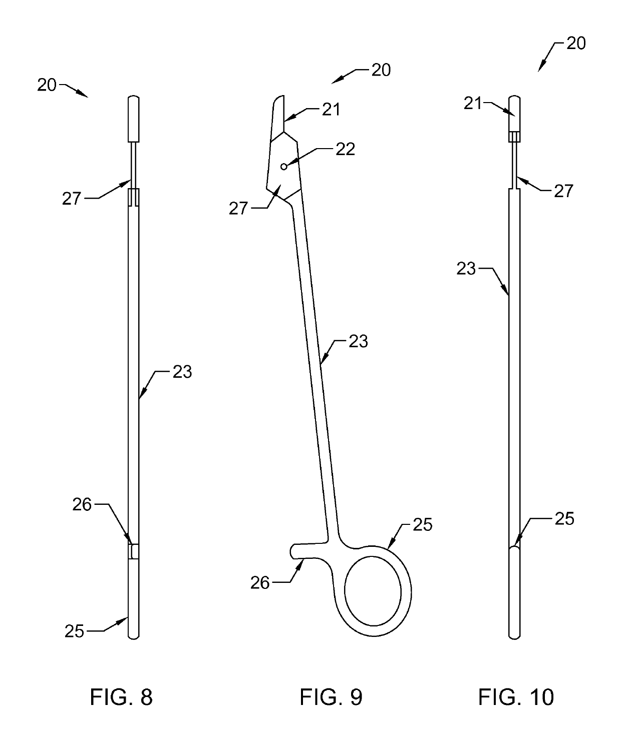
[0163]The first embodiment 10 of this invention describes an application of the invention on a standard set of needle holders (or needle drivers.) (FIG. 2) The apparatus consists of a pair of grasping jaws 21, 31 connected by a hinge 50 near the jaws. The proximal ends of the limbs are presented for use by the operator to open and close the grasping jaws of the device. (FIG. 4) Finger rings 25, 35 are most often desired on the proximal end. Separating and opposing the proximal limbs activates the jaws, strongly opening and closing them. Additionally, ratcheting locking teeth 26, 36 on the proximal end are desirable to allow the device to remain “locked” closed when the serrated teeth are engaged. They can be deactivated in the typical fashion by applying pressure slightly perpendicular to the plane of the limbs to disengage the teeth allowing the device to open again. Additionally, the invention employs a cutting device adjacent to the jaws of the instrument. This cutting limb 40 ma...
second embodiment
[0164]Surgical instruments including needle drivers come in a wide variety of sizes and lengths. These are advantageous for handling different surgical applications and wound depths from the suturing of skin to the deepest wounds including veterinary applications. A myriad of configurations are required for the enormous scope of tissues being addressed. Needle sizes vary from microscopic to very large and heavy enough to penetrate bone. The current invention is intended for the same wide variety of applications. The geometry of the design can be adjusted to accommodate the wide variety of applications. Specifically, for longer instruments, or for ergonomics, it may be desirable to have a trigger or lever activation of the cutting shear. This embodiment 110 can be accomplished as follows. Similar to the first embodiment the device consists of opposing grasping jaws 21, 131 preferably hinged distally. (FIG. 23) Preferably, finger rings 25, 135 and ratcheting locking teeth 26, 136 are ...
third embodiment
[0166]The same invention can be applied to microsurgical needle holders. The grasping jaws and cutting shear or shears can be sized and mounted onto microsurgical needle holders in the same fashion. (FIG. 41) The distal end preferably incorporates the new design of grasping and cutting while proximally the shape typically has more parallel limbs. The operator uses the grasping functions preferably by squeezing the limbs 220, 230 of the device between the fingers and thumb thus closing the working jaws. (FIG. 43) Typically there is a return spring 224, 234 on the limbs 220, 230 either squeezing force. For the new invention, the cutting shear 241 can be applied, typically rotating about the same main hinge 250 of the instrument 210. For activation it may be desirable to have a slide mechanism for easy use by the operator to engage the cutting function. This can be accomplished by having a slide 270 affixed to the convertible limb 230 of the instrument just proximal to the articulation...
PUM
 Abstract
Description
Claims
Application Information
 - R&D
- Intellectual Property
- Life Sciences
- Materials
- Tech Scout
- Unparalleled Data Quality
- Higher Quality Content
- 60% Fewer Hallucinations
Browse by: Latest US Patents, China's latest patents, Technical Efficacy Thesaurus, Application Domain, Technology Topic, Popular Technical Reports.
© 2025 PatSnap. All rights reserved.Legal|Privacy policy|Modern Slavery Act Transparency Statement|Sitemap|About US| Contact US: help@patsnap.com