
Surgical dilator, retractor and mounting pad

a technology of dilators and retractors, applied in the field of surgical dilators, retras, less invasive access portals, can solve the problems of distal end designs and do not conform to the natural shape of the spine, and achieve the effects of efficient safe and gentle sweeps, and effective mobilization of muscle fibers

Active Publication Date: 2019-09-17
CURITEVA INC
View PDF43 Cites 13 Cited by
  • Summary
  • Abstract
  • Description
  • Claims
  • Application Information

AI Technical Summary

Benefits of technology

The current retractor has limitations in its usability and may result in inconsistent results. The objective of this invention is to create a retractor that is more reliable, easy to use, and safe while providing a consistent result. Additionally, the walls of the retractor apply an opening force to the entire length, making the retraction process more robust.

Problems solved by technology

Current distal end designs are parallel to the spine and do not comply with the natural shape of the spine.

Method used


Image

  • Surgical dilator, retractor and mounting pad
  • Surgical dilator, retractor and mounting pad
  • Surgical dilator, retractor and mounting pad

Examples


Embodiment Construction

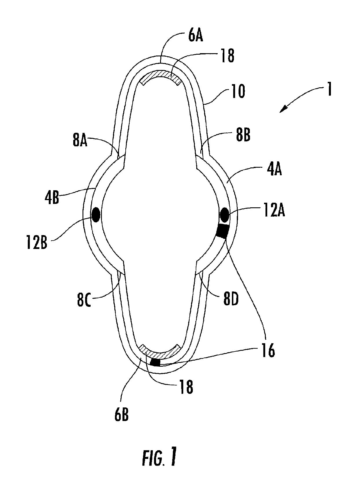
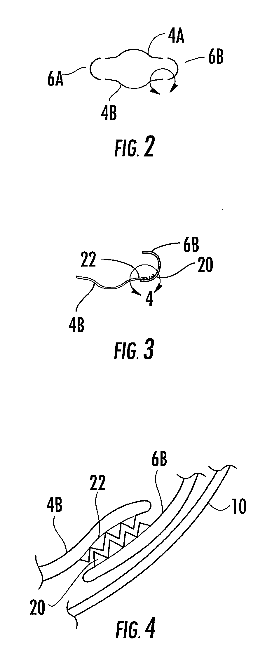
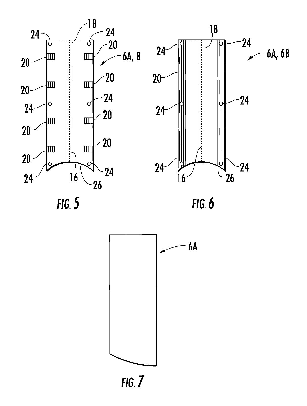
[0095]The present invention is directed to methods and devices for performing percutaneoous surgery and in particular spinal surgery. The surgery is performed through a portal or passageway provided by a retractor. The retractor is expandable in situ to thereby increase the size of the surgical area as well as the access thereto. It is particularly constructed to minimize trauma to tissue surrounding the retractor and the surgical area. The retractor can be used with any surgical approach to the spine such as; lateral, postero-lateral and / or antero-lateral, anterior, posterior, posterior mid-line, and in other regions of the body not associated with the spine.

[0096]FIG. 1 is a top view of retractor 1. As shown retractor 1 is comprised of four discrete segments. As shown, the segments consist of a pair of opposing semi cylindrical members 4A and 4B as well as a pair of opposing semi elliptical members 6A and 6B. A ratcheting mechanism 8A and 8C is located at each of the junctions bet...


PUM


Abstract

A retractor having an elongated body that provides access to a surgical location within a patient. The elongate body includes a plurality of segments that are connected to one another through a plurality of ratcheting mechanisms. The ratcheting mechanisms permit relative movement of the segments with respect to one another when expander dilators are inserted within the retractor. The segments are surrounded and retained by a resilient elastomeric sleeve or bands. The distal end surfaces of the segments include thin edges that are configured to mobilize, dissect, split and retract the terminal tissues in the surgical area. The retractor may be used in conjunction with a shim.

Description

CROSS-REFERENCE TO RELATED APPLICATIONS[0001]In accordance with 37 C.F.R. § 1.76, a claim of priority is included in an Application Data Sheet filed concurrently herewith. Accordingly, the present invention claims priority as a continuation-in-part of U.S. patent application Ser. No. 14 / 838,599, entitled “Surgical Dilator, Retractor and Mounting Pad”, filed Aug. 28, 2015, which application is a continuation-in-part of U.S. patent application Ser. No. 14 / 524,811, entitled “Surgical Dilator, Retractor and Mounting Pad”, filed Oct. 27, 2014, now U.S. Pat. No. 9,585,648, issued Mar. 7, 2017, which application is a continuation of U.S. patent application Ser. No. 13 / 932,735, entitled “Surgical Dilator, Retractor and Mounting Pad”, filed Jul. 1, 2013, now U.S. Pat. No. 8,870,760, issued Oct. 28, 2014, which application is a divisional of U.S. patent application Ser. No. 12 / 541,617, entitled “Surgical Dilator, Retractor and Mounting Pad”, filed Aug. 14, 2009, now U.S. Pat. No. 8,480,704, i...

Claims


Application Information

Patent Timeline
Patent Type & Authority Patents(United States)
IPC IPC(8): A61B17/02A61B1/32A61M29/00A61B17/34A61B17/00A61B90/30A61B90/00
CPCA61B17/0218A61B1/32A61M29/00A61B17/0293A61B17/3423A61B17/025A61B17/3439A61B2090/306A61B2090/3966A61B2017/00407A61B2017/0256A61B17/02A61B2017/3488A61B2017/00039A61B2017/3419
Inventor HEIGES, BRADLEY A.LANE, II, DAVID E.
Owner CURITEVA INC
Learn More