Optical apparatus with rotational operating member

a technology of rotating operating member and optical apparatus, which is applied in the direction of optics, mountings, instruments, etc., can solve the problems of operating quality, large force required to perform the zooming operation, and actual composition to differ from an intended composition, so as to improve the operating quality of the rotational operating member and low cost

Active Publication Date: 2019-09-10
CANON KK
View PDF10 Cites 0 Cited by
  • Summary
  • Abstract
  • Description
  • Claims
  • Application Information

AI Technical Summary

Benefits of technology

[0005]The present invention provides an optical apparatus which is equipped with a lens capable of being moved forward or backward in a direction of an optical axis by operating a rotational operating member, prevents unintended motions from occurring in the lens, and improves operating quality of the rotational operating member at low cost.
[0007]According to the present invention, the optical apparatus equipped with the lens capable of being moved forward or backward in the direction of the optical axis by operating the rotational operating member prevents unintended motions from occurring in the lens and improves operating quality of the rotational operating member at low cost.

Problems solved by technology

When a zooming operation is performed with an image pickup apparatus, which is equipped with a lens barrel having a heavy zoom lens group, pointing upward or downward, unintended zooming may occur due to lens' own weight, causing an actual composition to differ from an intended composition.
However, when the operating member is urged using the elastic member, large force is required to perform the zooming operation.
Particularly when the heavy zoom lens group is driven using a cam mechanism in zooming, a problem arises due to operating quality compromised in an area where large operating force is required such as an area where cams are steep.
For this reason, areas where different operating forces are required exist within the whole operating range of the rotational operating ring, and this compromises operating quality.
Moreover, the adjusting mechanism described in Japanese Laid-Open Patent Publication (Kokai) No. 2015-31774 has a problem of high cost due to a complicated structure required to displace the elastic member.

Method used


Image

  • Optical apparatus with rotational operating member
  • Optical apparatus with rotational operating member
  • Optical apparatus with rotational operating member

Examples


Embodiment Construction

[0021]Hereafter, embodiments of the present invention will be described in detail with reference to the drawings. In the following description of the embodiments, a lens barrel which an image pickup apparatus such as a digital camera has is taken as an example of an optical apparatus according to the present invention, but the optical apparatus according to the present invention is not limited to this.

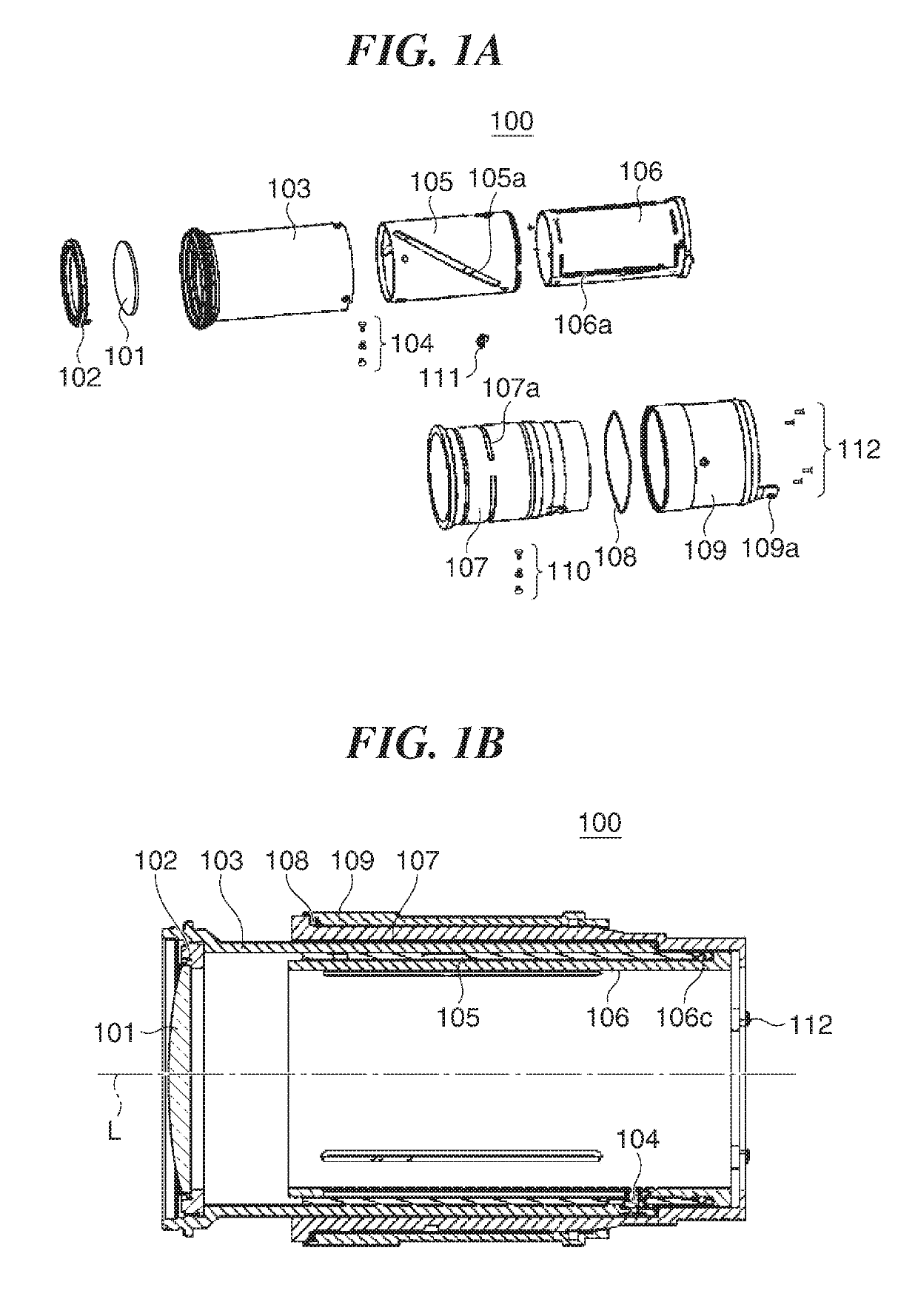
[0022]A description will now be given of the first embodiment of the present invention. FIG. 1A is an exploded perspective views showing a lens barrel 100 according to the first embodiment of the present invention. FIG. 1B is a cross-sectional view showing the lens barrel 100. The lens barrel 100 has a lens group 101, a lens holding member 102, a holding cylinder 103, engaging members 104, a guide member 105, a straight-ahead guide member 106, a fixing member 107, a pressing member 108, and a rotational operating member 109 (hereafter referred to “the operating member 109”).

[0023]The l...


PUM


Abstract

An optical apparatus which has a lens movable forward or backward in a direction of an optical axis through operation of an operating member, prevents unintended motions in the lens, and improves operating quality of the operating member at low cost. A fixing member rotatably holds the operating member and has a first contact surface coming into contact with a pressing member sandwiched between the operating member and the fixing member. The operating member rotatable about the optical axis moves an image pickup optical system in the direction of the optical axis and has a second contact surface facing the first contact surface and coming into contact with the pressing member. The pressing member applies pressing force as load on the operating member to the operating member. The first or second contact surface has a slope that changes the pressing force according to a rotational angle of the operating member.

Description

BACKGROUND OF THE INVENTIONField of the Invention[0001]The present invention relates to an optical apparatus with a rotational operating member.Description of the Related Art[0002]When a zooming operation is performed with an image pickup apparatus, which is equipped with a lens barrel having a heavy zoom lens group, pointing upward or downward, unintended zooming may occur due to lens' own weight, causing an actual composition to differ from an intended composition. To prevent such unintended zooming, there is known an arrangement in which an operating member for performing a zooming operation is urged using an elastic member to apply torque acting as a brake. However, when the operating member is urged using the elastic member, large force is required to perform the zooming operation. Particularly when the heavy zoom lens group is driven using a cam mechanism in zooming, a problem arises due to operating quality compromised in an area where large operating force is required such a...

Claims


Application Information

Patent Timeline
Patent Type & Authority Patents(United States)
IPC IPC(8): G02B7/04G02B15/15G02B7/10G02B7/02G02B7/09
CPCG02B7/04G02B7/023G02B15/15G02B7/10G02B7/09
Inventor ITO, HIROKI
Owner CANON KK
Why Eureka
Try Eureka