
Metal cabinet with electrically conductive hinges

a technology of electrically conductive hinges and metal cabinets, which is applied in the field of metal cabinets, can solve the problems of increasing cost, complex wiring structure, and lowering assembly efficiency, and achieve the effect of facilitating assembly and reducing cos

Active Publication Date: 2019-09-10
FULSUN HOME IMPROVEMENT
View PDF21 Cites 0 Cited by
  • Summary
  • Abstract
  • Description
  • Claims
  • Application Information

AI Technical Summary

Benefits of technology

This patent is about a metal cabinet with electrically conductive hinges. This invention has the advantage of simple structure and low cost. The first hinge is connected to the negative electrode of the LED luminous body, and the second hinge is connected to the positive electrode. The power supply is connected to the first hinge through an electrically conductive wire, and the LED luminous body is connected to the second hinge through another electrically conductive wire. This avoids the possibility of short circuits. The inner insulation pad is placed between the hinge and the cabinet body or the cabinet door to insulate them. The design of the structure is not only safe but also prevents short circuits and ensures the product quality.

Problems solved by technology

Traditional cabinets realize electrification by adopting a long wire disposed in the cabinet door and the cabinet body, this design needs many fasteners, making the wiring structure complex, lowering the assembly efficiency and increasing the cost.
Moreover, part of wire will be inevitably exposed at the joint of the cabinet door and the cabinet body, which is neither beautiful, nor convenient to clean.

Method used


Image

  • Metal cabinet with electrically conductive hinges
  • Metal cabinet with electrically conductive hinges
  • Metal cabinet with electrically conductive hinges

Examples


Embodiment Construction

[0026]The present disclosure is further described below in detail with reference to accompanying drawings.

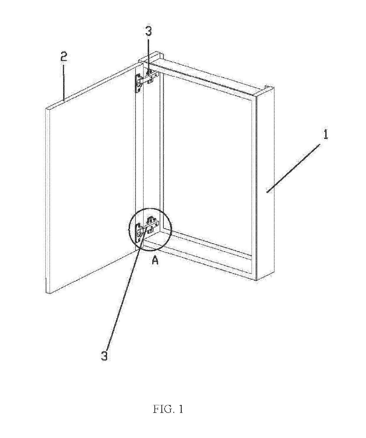
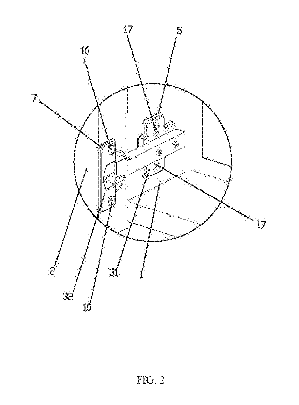
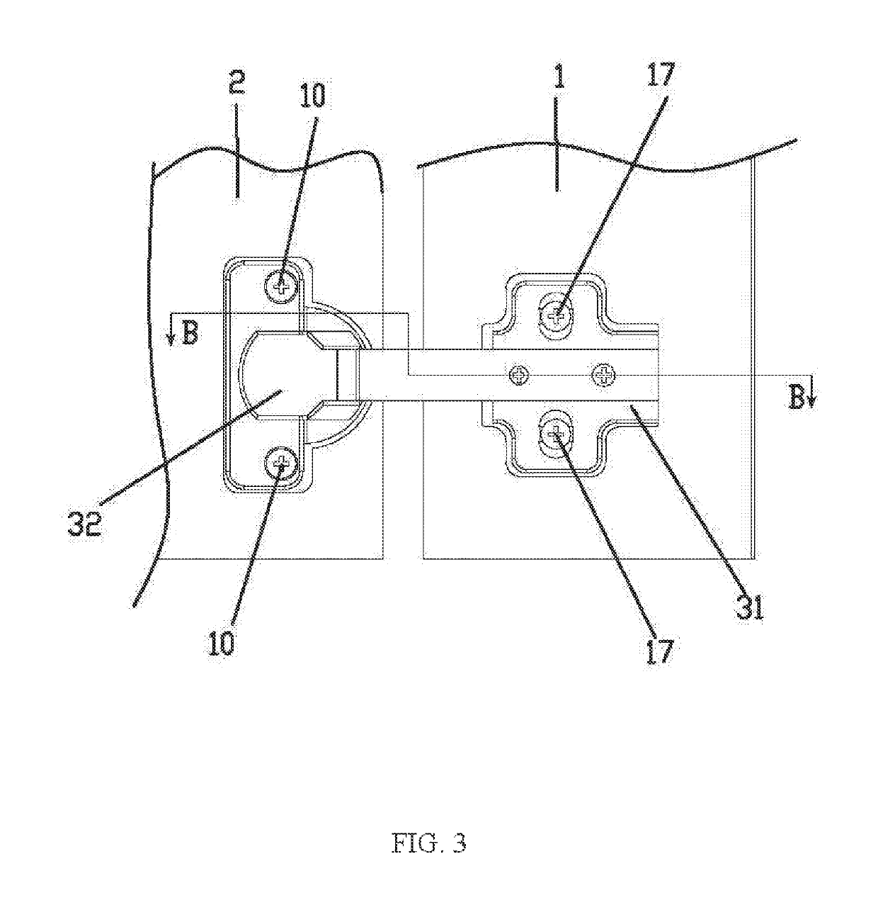
[0027]Referring to FIG. 1 to FIG. 5, a metal cabinet with electrically conductive hinges, comprises a cabinet body 1 and a cabinet door 2 that are made of an electrically conducive metal. An LED luminous body (not showing in accompanying drawings) is disposed in the cabinet door 2. At least two electrically conductive hinges 3 for enabling the cabinet door 2 to rotate relative to the cabinet body 1 are disposed between the cabinet door 2 and the cabinet body 1, at least one of the hinges 3 is connected to a negative electrode of the LED luminous body, and at least one of the hinges 3 is connected to a positive electrode of the LED luminous body. The hinges 3 comprise a first hinge body 31 fixedly connected to the cabinet body 1 and a second hinge body 32 fixedly connected to the cabinet door 2. The first hinge body 31 is connected to a first electrically conductive wire 4 connec...


PUM


Abstract

A metal cabinet with electrically conductive hinges comprises a cabinet body and a cabinet door that are made of an electrically conductive metal. An LED luminous body is disposed in the cabinet door, and at least two electrically conductive hinges for enabling the cabinet door to rotate relative to the cabinet body are disposed between the cabinet door and the cabinet body. Each of the hinges comprises a first hinge body and a second hinge body. The first hinge body is connected to a first electrically conducts wire connecting the first hinge body to a power supply. A first outer insulation pad is disposed between the first hinge body and the cabinet body. The second hinge body is connected to a second electrically conductive wire connecting the second hinge body to the LED luminous body. A second outer insulation pad is disposed between the second hinge body and the cabinet door.

Description

CROSS-REFERENCE TO RELATED APPLICATIONS[0001]This application is a continuation of International Patent Application No. PCT / CN2017 / 077737 with a filing date of Mar. 22, 2017, designating the United States, now pending, and further claims priority to Chinese Patent Application No. 201620502001.0 with a filing dale of May 27, 2016. The content of the aforementioned applications, including any intervening amendments thereto, are incorporated herein by reference.TECHNICAL FIELD[0002]The disclosure relates to a metal cabinet, and particularly to a metal cabinet with electrically conductive hinges.BACKGROUND OF THE PRESENT INVENTION[0003]At present, the metal cabinets are widely applied in bathroom. The metal cabinet is usually installed on the wall, and personal hygiene products like shampoo, toothpaste, etc. are placed in the cabinet. Generally, an LED luminous body will be disposed inside the cabinet door, which can brighten the whole cabinet after electrification. Traditional cabinets...

Claims


Application Information

Patent Timeline
Patent Type & Authority Patents(United States)
IPC IPC(8): E05D11/00E05D3/14F21V33/00E06B7/28F21V23/00A47B67/00F21Y115/10
CPCE05D11/0081E05D3/142E05D11/00F21V23/001F21V33/0012F21Y2115/10E05Y2800/106A47B67/005E06B7/28E05Y2900/20E05Y2900/208
Inventor ZHU, LINGLU, MAOLIN
Owner FULSUN HOME IMPROVEMENT
Learn More