
Needle unit for drug delivery device

a drug delivery and needle unit technology, applied in the direction of intravenous devices, infusion needles, other medical devices, etc., can solve the problems of cross-contamination risk, needle clogging, needle abrasion, etc., and achieve the effect of reducing or eliminating at least one drawback

Inactive Publication Date: 2019-09-10
NOVO NORDISK AS
View PDF14 Cites 0 Cited by
  • Summary
  • Abstract
  • Description
  • Claims
  • Application Information

AI Technical Summary

Benefits of technology

[0009]It is an object of the invention to eliminate or reduce at least one drawback of the prior art, or to provide a useful alternative to prior art solutions.
[0010]In particular, it is an object of the invention to provide a needle unit having a configuration which enables it to be prevented from being used on more than one injection device, or used more than once.

Problems solved by technology

However, some people ignore this recommendation and consciously decide to use the same needle assembly again and again.
Even with such a solution, however, excessive use of the needle cannula may lead to other issues such as e.g. needle clogging and / or needle abrasion.
Furthermore, the risk of cross-contamination arising from different users sharing the same needle cannula by using it on their respective injection devices is still present.
However, the spreader is a separate element which is displaced to an inactive position during attachment of the drug delivery device, i.e. the solution requires an additional constructional part which is rendered useless upon the initial use of the dispense interface, adding to the production costs.
None of these prior art lockout solutions appear to be useable for conventional injection systems within diabetes care, where e.g. a pen type injection device is provided with a threaded interface and configured to receive an injection needle assembly with a mating thread, as they are both designed for use in a system where the drug delivery device and the dispense interface are attached, respectively detached, by simple axial relative motion.

Method used


Image

  • Needle unit for drug delivery device
  • Needle unit for drug delivery device
  • Needle unit for drug delivery device

Examples


Embodiment Construction

[0042]When in the following relative expressions, such as “clockwise” and “counter-clockwise”, are used, these refer to the appended figures and not necessarily to an actual situation of use. The shown figures are schematic representations for which reason the configuration of the different structures as well as their relative dimensions are intended to serve illustrative purposes only. Specifically, any rotational motion is described as observed when looking in the distal direction, i.e. as seen from the left side of the figure.

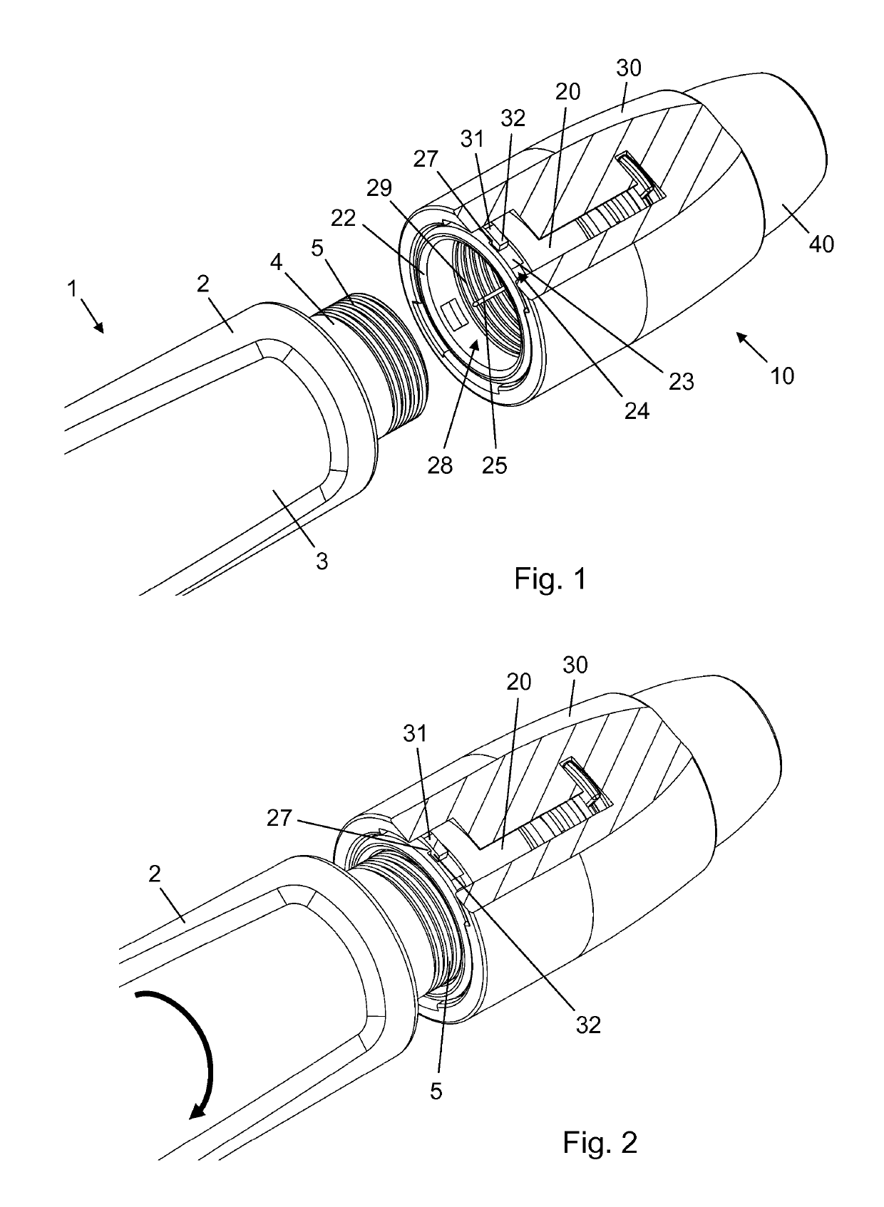
[0043]FIG. 1 is a perspective view of a needle unit 10 according to a preferred embodiment of the invention. The needle unit 10 is shown just distally of a distal end portion of an injection pen 1 which is ready for attachment to the needle unit 10.

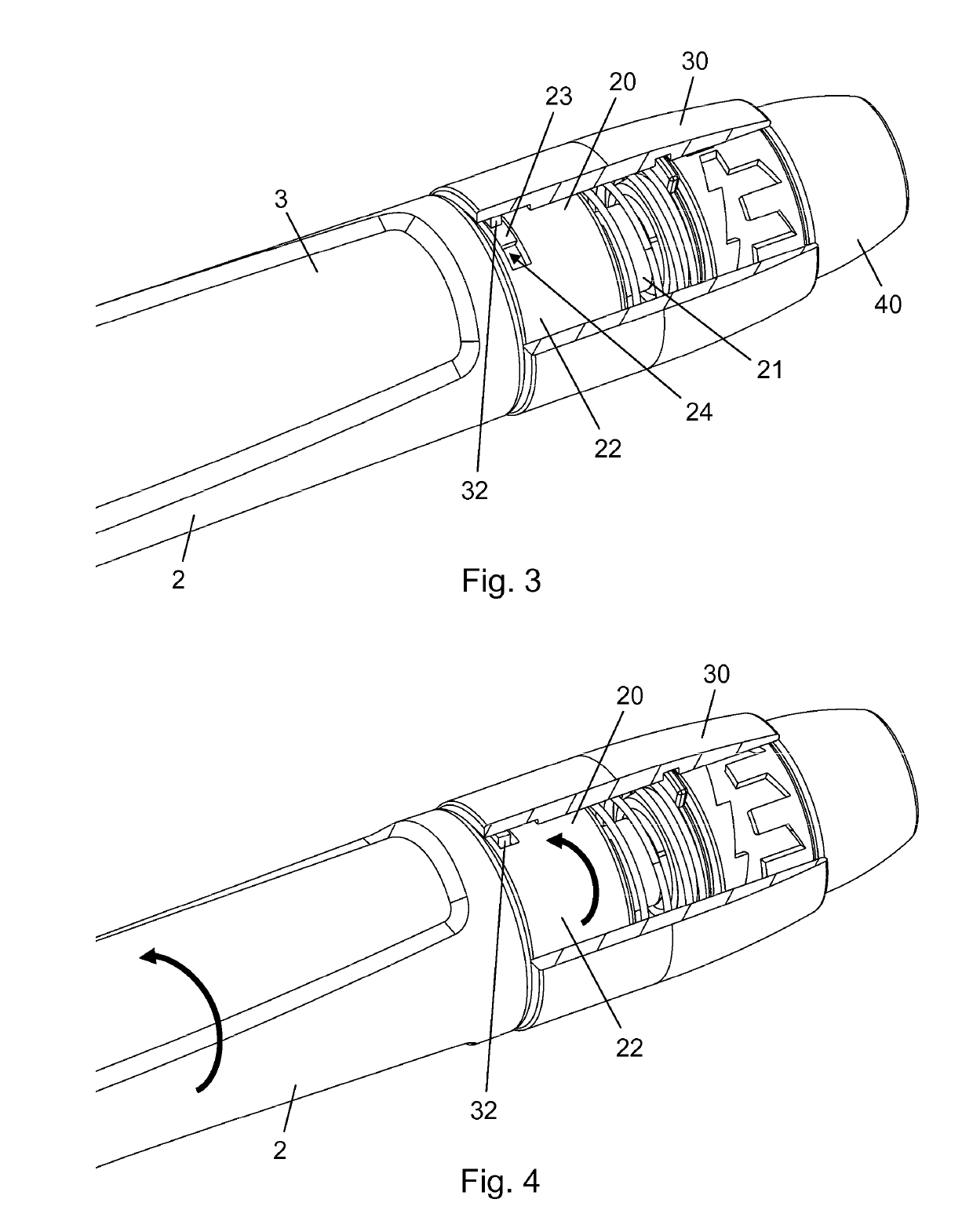
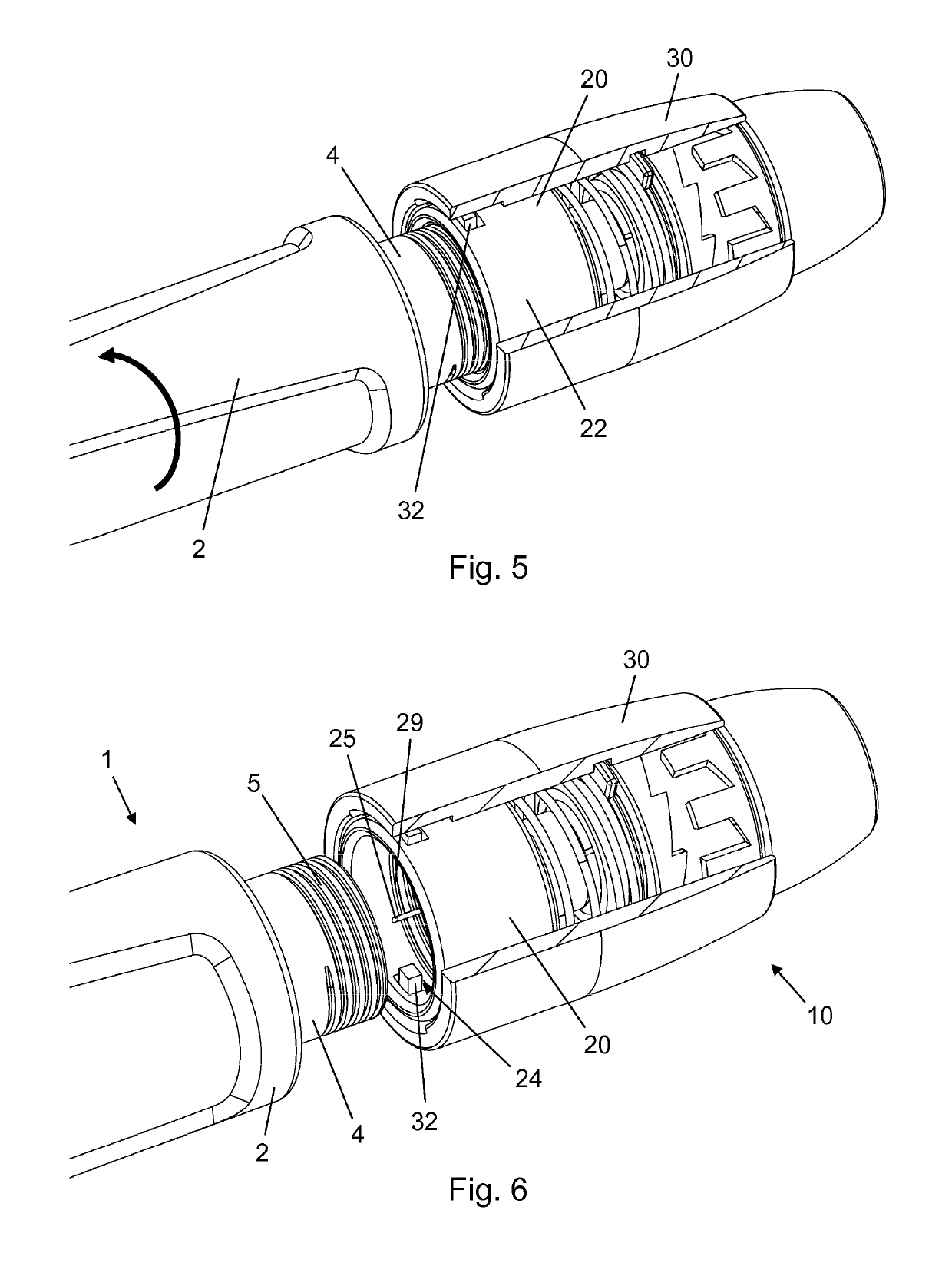
[0044]The needle unit 10 comprises a needle assembly 20, an outer cover 30 surrounding the needle assembly 20, and a needle shield 40. The needle assembly 20 comprises a needle hub 21 (see FIG. 3) in which an inje...


PUM


Abstract

The present invention provides an injection needle unit (10) comprising: a needle assembly (20) comprising: an injection needle (25) extending along a longitudinal axis and having a distal needle end configured for insertion into a subject and a proximal needle end configured for penetration of a reservoir septum, and a skirt (22) surrounding the proximal needle end and defining a receiving space (28) for reception of a needle mount of a drug delivery device, the skirt (22) comprising a slot (24), and a block structure (32) supported exteriorly of the skirt (22), wherein the block structure (32) is biased towards the longitudinal axis and is capable of radial displacement through the slot (24) from a latched position outside the receiving space (28) to a released position within the receiving space (28).

Description

CROSS-REFERENCE TO RELATED APPLICATIONS[0001]This application is a 35 U.S.C. § 371 National Stage application of International Application PCT / EP2016 / 053552 (published as WO 2016 / 131954), filed Feb. 19, 2016, which claims priority to European Patent Application 15155941.6, filed Feb. 20, 2015; the contents of which are incorporated herein by reference.FIELD OF THE INVENTION[0002]The present invention relates to needle units for use with drug delivery devices to convey drug from a reservoir to an administration site.BACKGROUND OF THE INVENTION[0003]Administration of medication contained in sealed reservoirs often involves a penetration of the reservoir seal. For example, people with diabetes using pen injection systems for self-administration of insulin or GLP-1 attach a needle assembly comprising an injection needle to the pen injector, whereby a reservoir closure is transpierced by the injection needle, and subsequently operate the pen injector to expel a dose of medication through...

Claims


Application Information

Patent Timeline
Patent Type & Authority Patents(United States)
IPC IPC(8): A61M5/32A61M5/50A61M5/34
CPCA61M5/3293A61M5/3272A61M5/3286A61M5/347A61M5/50A61M2205/273A61M5/3245A61M2005/3254A61M2005/3267
Inventor BENGTSSON, HENRIKSPORK, EMIL GRAMEILERTSEN, LARS
Owner NOVO NORDISK AS
Learn More