Printing device and control method of a printing device

a printing device and control method technology, applied in printing, other printing apparatus, etc., can solve the problems of motor overheating, detection of upper limit error, and stoppage of web conveyance mechanism, so as to reduce the frequency of starting and stopping the reel driver, reduce the load on the reel driver, and reduce the control method

Inactive Publication Date: 2019-09-03
SEIKO EPSON CORP
View PDF9 Cites 2 Cited by
  • Summary
  • Abstract
  • Description
  • Claims
  • Application Information

AI Technical Summary

Benefits of technology

[0011]Because the reel driver in this configuration maintains a specific speed when the amount of slack is between the first threshold and second threshold, the reel driver can be driven at a constant speed for a long time if there is a sufficient difference between the first threshold and second threshold. More specifically, the frequency of starting and stopping driving the reel driver can be reduced, and the load on the reel driver can be reduced. Furthermore, because the speed is changed to the second speed when the detected amount of slack is less than the second threshold and the reel driver is driving at the first speed, the amount of slack can be quickly increased to greater than the second threshold. As a result, a desirable amount of slack can be maintained in the print medium by a simple control method. Furthermore, because the reel driver is stopped when the detected amount of slack is less than the second threshold and the reel driver is driving at the second speed, action to prevent an undesirable slack state, such as damage to the reel driver or the end of the print medium, can be quickly taken. Furthermore, because the slack is formed in the space below the roll of print medium, a space-efficient, simple slack housing can be easily constructed.
[0012]It will also be obvious that by creating slack in the rolled print medium, the inertial load (back tension) on the delivery reel side that works on the media conveyance unit can be reduced, and the print medium can be reliably fed with good precision by the media conveyance unit.
[0015]This configuration enables, by a simple configuration, accurately detecting the amount of slack (first threshold and second threshold) in the print medium.
[0017]This configuration enables conveying the print medium until the end of the print medium reaches the media conveyance unit even after the end of the print medium is detected. Print medium waste can therefore be reduced.
[0019]This configuration enables conveying the print medium until the end of the print medium reaches the media conveyance unit even after the end of the print medium is detected, and printing can continue without waste.

Problems solved by technology

When the first sensor does not detect the air loop during first air loop control, and when the second sensor does not detect the air loop during second air loop control, an upper limit error is detected and the web conveyance mechanism is stopped.
As a result, the motor may overheat.

Method used


Image

  • Printing device and control method of a printing device
  • Printing device and control method of a printing device
  • Printing device and control method of a printing device

Examples


Embodiment Construction

[0025]Preferred embodiments of a printing device and control method of a printing device according to the present invention are described below with reference to the accompanying figures. The printing device in this embodiment is a label printer that prints by an inkjet method while delivering and conveying print media (label paper) from a paper roll.

Configuration of the Printing Device

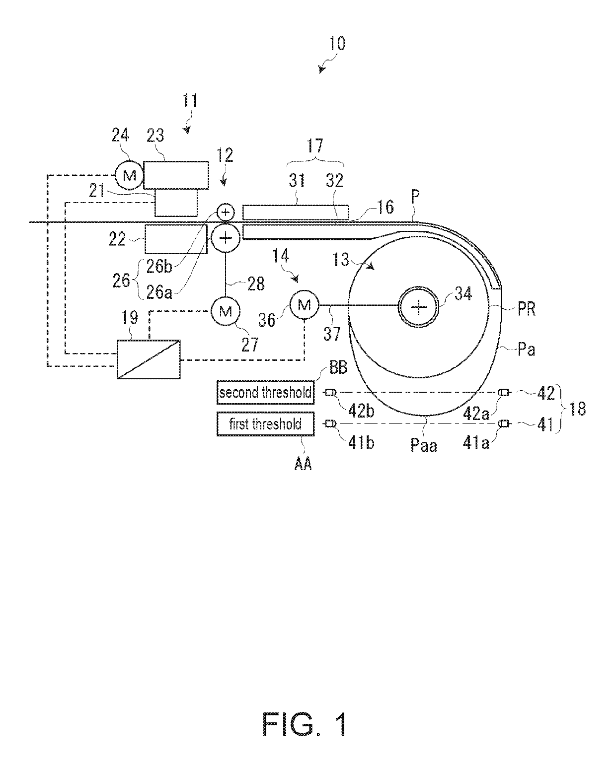
[0026]FIG. 1 illustrates the configuration of main parts of the printing device according to the invention. As shown in the figure, the printing device (printer) 10 has a print unit 11 that prints on the print medium P by an inkjet method; a media conveyor 12 that conveys the print medium P to the print unit 11; a delivery reel 13 that delivers the print medium P wound into a roll (media roll PR) toward the media conveyor 12; and a reel driver 14 that drives the delivery reel 13.

[0027]The reel driver 14 drives the delivery reel 13 rotationally, and the delivery reel 13 delivers the print medium P with...


PUM


Abstract

A printing device reduces the load on the reel driver that drives a delivery reel. A controller drives a reel driver to turn at multiple drive speeds, including a minimum speed at which the circumferential speed of a media roll of the largest diameter is equal to, and a maximum speed at which the circumferential speed of a media roll of the smallest diameter is equal to, the conveyance speed of the media conveyor. When the amount of slack detected by a slack detector goes from between a first threshold and a second threshold that is less than the first threshold, to an amount of slack less than the first threshold, the controller changes the drive speed to one higher speed if the reel driver is not turning at the maximum speed, and stops the reel driver if the reel driver is turning at the maximum speed.

Description

CROSS REFERENCE TO RELATED APPLICATION[0001]The present application claims priority under 35 U.S.C. § 119 to Japanese Patent Application No. 2016-067507 filed on Mar. 30, 2016 in Japan. The disclosure of which is incorporated herein by reference in its entirety.BACKGROUND1. Technical Field[0002]The present invention relates to a printing device and control method of a printing device that delivers rolled print media for printing.2. Related Art[0003]Printing devices (printers) that deliver and convey a web from a web roll of a continuous web wound into a roll, and form images by an electrophotographic method, are known from the literature. See, for example, JP-A-2013-63821.[0004]The printer described in JP-A-2013-63821 has a paper feed device that supports a web roll so that the web can be delivered therefrom; an air loop mechanism that forms an air loop (slack) in the web delivered from the paper feed device; a web conveyance mechanism that is located downstream from the air loop me...

Claims


Application Information

Patent Timeline
Patent Type & Authority Patents(United States)
IPC IPC(8): B41J15/00
CPCB41J15/005B41J15/02B41J29/38
Inventor KAWAJIRI, MASAHIRO
Owner SEIKO EPSON CORP
Why Eureka
Try Eureka