
Ultrasonic surgical instrument assembly, related accessory, and associated surgical method

a surgical instrument and ultrasonic technology, applied in the field of ultrasonic surgical instrument assembly, can solve the problems of unfavorable tissue damage, steep learning curve, etc., and achieve the effects of facilitating tissue perception, facilitating tissue visualization, and facilitating enhanced care and attention

Active Publication Date: 2019-09-03
MISONIX INC
View PDF22 Cites 0 Cited by
  • Summary
  • Abstract
  • Description
  • Claims
  • Application Information

AI Technical Summary

Benefits of technology

[0009]It is a more specific object of the present invention to provide such an instrument assembly which facilitates an enhanced degree of care and attention in carrying out medical, e.g., ultrasonic surgical, procedures.
[0010]It is an even more particular object of the present invention to provide such an instrument assembly that facilitates perception of tissues at a surgical site.
[0011]A related object of the present invention is to provide an accessory utilizable with a medical instrument that facilitates visualization of tissues at a target tissue site.
[0012]A more specific object of the present invention is to provide a surgical method using an ultrasonic surgical instrument, wherein visualization of tissues at a surgical site is enhanced or facilitated.
[0013]An even more specific object of the present invention is to provide a medical instrument assembly and / or associated medical method wherein the meeting of power supply requirements is facilitated.
[0024]Pursuant to another feature of the present invention, the surgical method further comprises removably mounting the power supply at least indirectly to the handpiece. Where the power supply includes a coil, the removable mounting of the power supply at least indirectly to the handpiece includes disposing the coil about a power cable feeding the transducer or vibration generator. Where the power supply further includes a slow-drain capacitor operatively connected to the coil, the surgical method further comprises operating the capacitor to provide illumination energy to the light source for a predetermined period of time after a termination of power conduction through the cable.

Problems solved by technology

After some experience, competent surgeons were able to master the technique, but the learning curve was steep.
However, this very effectiveness can result in unwanted damage to organic tissues, for instance, when operating conditions are such that a sufficient degree of care cannot be properly exercised.
This may happen, for instance, when the surgical site is not properly illuminated.

Method used


Image

  • Ultrasonic surgical instrument assembly, related accessory, and associated surgical method

Examples


Embodiment Construction

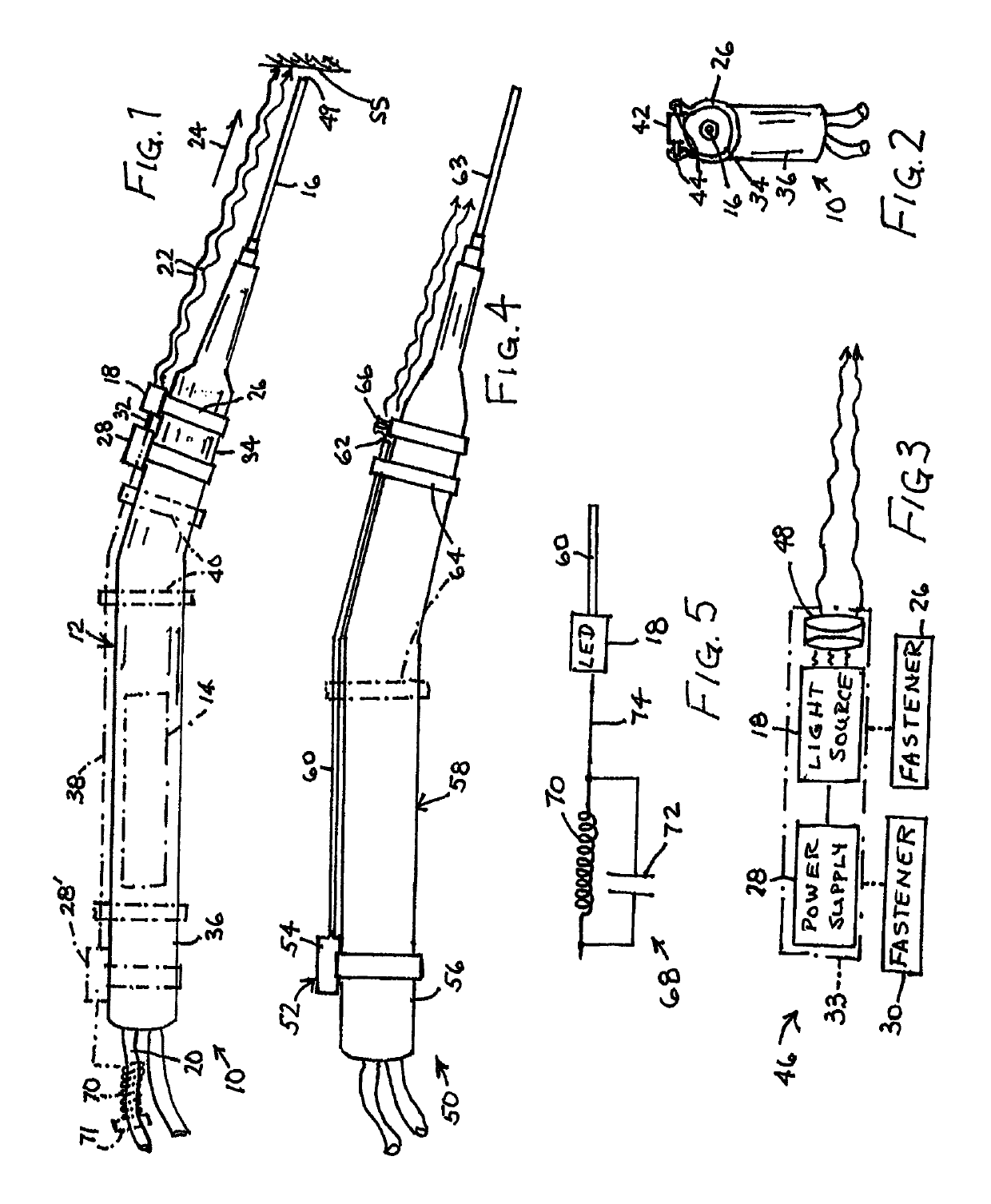
[0032]As shown in FIGS. 1 and 2, an ultrasonic surgical instrument assembly 10 comprises a handpiece 12, a generator 14 of ultrasonic mechanical vibrations, a probe 16, and a light source 18. Generator 14 is encased in handpiece 12 and typically takes the form of an electromechanical transducer such as a piezoelectric crystal stack. Generator is energized by an alternating electrical waveform of ultrasonic frequency carried by a power transmission cord or cable 20 extending to the generator via a rear or proximal end 36 of the handpiece.

[0033]Probe 16 is shown as a tubular member but may take any form conducive to the applications of ultrasonic mechanical vibrations to organic tissues. Thus, probe 16 may exemplarily take the form of a planar cutting blade as disclosed in U.S. Pat. No. 6,379,371, a lipectomy probe as disclosed in U.S. Pat. No. 5,527,273, or a debrider tool as disclosed in U.S. Pat. No. 7,931,611. Probe 16 is attached to a distal end of handpiece 12 and is operatively...


PUM


Abstract

An ultrasonic surgical instrument assembly includes a handpiece, a generator of ultrasonic mechanical vibrations disposed in the handpiece, a probe, and a light source. The probe is attached to a distal end of the handpiece and is operatively connected to the generator. The light source is removably attached to the handpiece and is configured and mounted to direct at least visible electromagnetic radiation in a direction along the probe so as to illuminate a surgical site distal of the probe.

Description

BACKGROUND OF THE INVENTION[0001]This invention relates to an ultrasonic surgical instrument assembly. This invention also pertains to an accessory for use with an ultrasonic surgical instrument. This invention additionally related to an associated surgical method.[0002]Over the past 30 years, several ultrasonic tools have been invented which can be used to ablate or cut tissue in surgery. Wuchinich et al. in U.S. Pat. No. 4,223,676 and Idemoto et al in U.S. Pat. No. 5,188,102 disclose such devices.[0003]Ultrasonic surgical devices generally fall into two categories. One is a blunt tip hollow probe that vibrates at frequencies between 20 kc and 100 kc, with amplitudes up to 300 microns or more. Such devices ablate tissue by either producing cavitation bubbles which implode and disrupt cells, tissue compression and relaxation stresses (sometimes called the jackhammer effect) or by other forces such as microstreaming of bubbles in the tissue matrix. The effect is that the tissue becom...

Claims


Application Information

Patent Timeline
Patent Type & Authority Patents(United States)
IPC IPC(8): A61B17/00A61B90/30A61B18/00A61B17/32
CPCA61B90/30A61B17/320068A61B2018/00178A61B2090/309A61B2017/00477A61B2017/320069
Inventor DARIAN, ALEXANDER
Owner MISONIX INC
Learn More