
Power distribution clip assembly

a technology of fuse clip and assembly, which is applied in the direction of connection, emergency protection device, electrical equipment, etc., can solve the problems of relatively high construction cost, relatively expensive construction, and relatively complex design of fuse clip assembly, and achieves simple, effective and reliable connection, and reduces the cos

Active Publication Date: 2019-08-13
ILSCO
View PDF16 Cites 0 Cited by
  • Summary
  • Abstract
  • Description
  • Claims
  • Application Information

AI Technical Summary

Benefits of technology

The solution provides a simple, reliable, and cost-effective connection with improved integrity, quality, and fatigue strength, allowing for faster installation and reduced costs by integrating the functions of a fuseholder and terminal block into a single compact device.

Problems solved by technology

Relatively complex designs have been used in connection with the fuse clip assemblies employing a substantial number of different components.
Prior art devices have also generally not been conducive to small, compact construction while maintaining the necessary electrical characteristic, and in many cases, have been relatively costly to construct.

Method used


Image

  • Power distribution clip assembly
  • Power distribution clip assembly
  • Power distribution clip assembly

Examples


Embodiment Construction

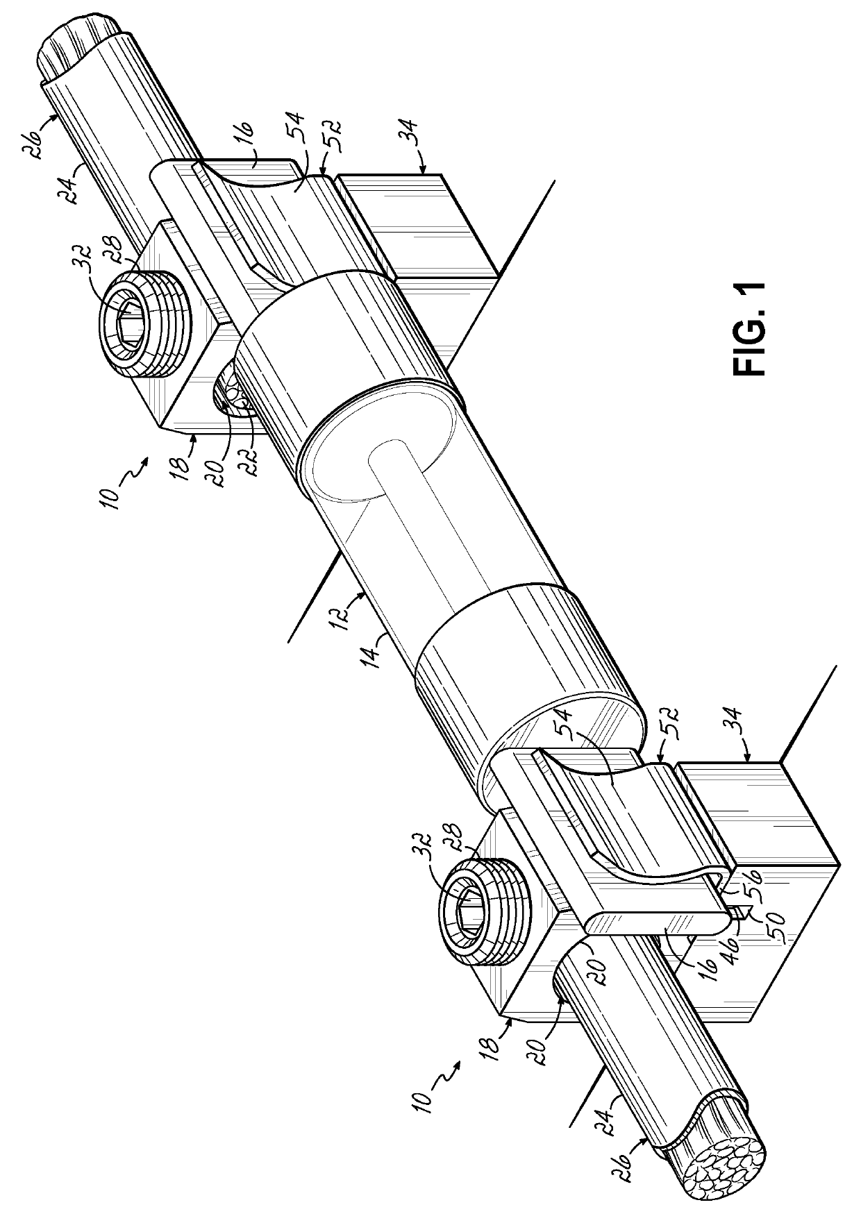
[0018]Referring to FIG. 1, one embodiment of a power distribution fuse clip assembly 10 according to this invention is shown. The assembly 10 of FIG. 1 is utilized to mount a standard blade or barrel type fuse 12. The fuse 12 includes a fuse body 14 with opposing contact ends which in one form are blades 16 extending longitudinally from the fuse body 14. The blades 16 are generally planar and adapted to mount into one of two fuse clip assemblies 10 according to various embodiments of this invention.

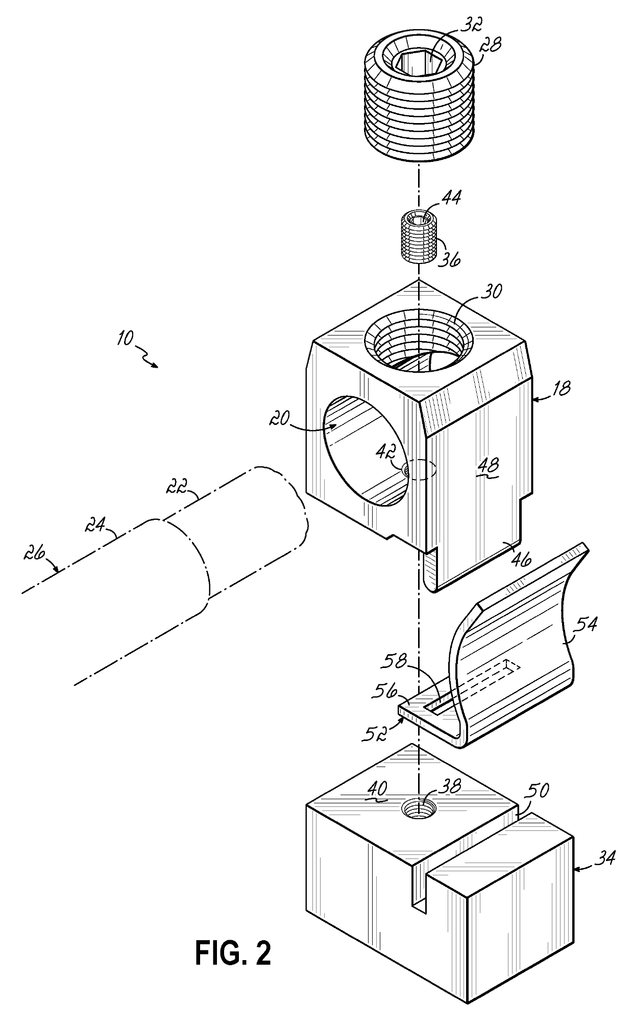
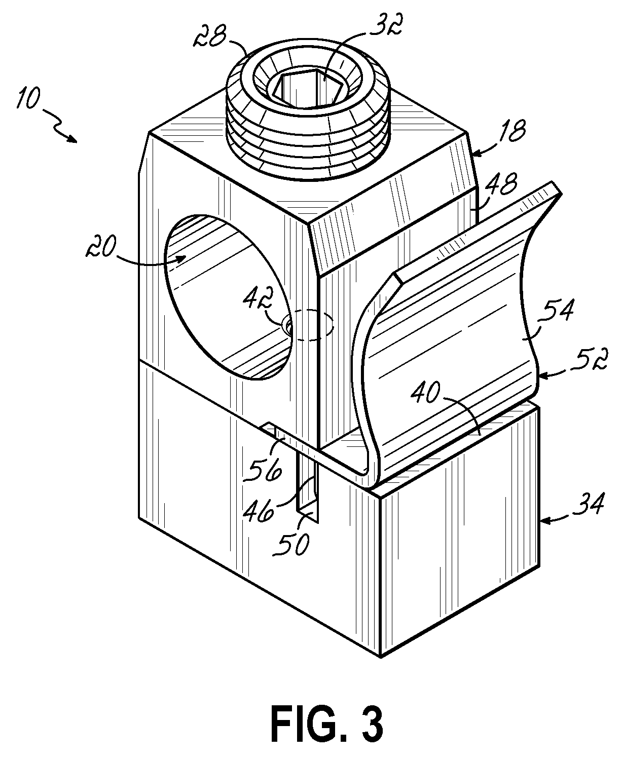
[0019]Referring more particularly to FIGS. 2-4, the fuse clip assembly 10 according to embodiments of this invention includes a lug 18 which has a conductor receiving arrangement which in one embodiment is a port 20 to receive the exposed strands of wire 22 projecting from a sheath 24 of the conductor 26. Once the wire strands 22 are inserted into the conductor port 20, a conductor retainer which in one embodiment is a set screw 28 is received within a set screw threaded aperture 30 of th...


PUM


Abstract

A power distribution assembly which may be a fuse clip or a switch includes a lug mounted to a block in association with a spring clip which confronts one side of the lug. A portion of the spring clip is mounted to the block and an upper spring arm of the clip is positioned on one side of the lug. The lug is mounted to the block and includes a downwardly projecting tang which is inserted through a slot in the bottom portion of the assembly to thereby couple the spring arm to the lug and block and to receive the end of the fuse or a blade between the spring arm and the lug.

Description

[0001]This claims the benefit of U.S. Provisional Patent Application Ser. No. 62 / 425,113, filed Nov. 22, 2016 and hereby incorporated by reference in its entirety.BACKGROUND OF THE INVENTION[0002]This invention relates generally to power circuit distribution devices, and more particularly to fuseholders for connecting overcurrent protection fuses to electrical circuitry.[0003]Electrical systems typically include of circuit protection devices that protect electrical circuitry, equipment, and components from damage. Overcurrent protection devices, for example, are constructed to physically open or interrupt a circuit path and isolate electrical components from damage upon the occurrence of specified overcurrent conditions in the circuit. Known circuit protection devices include devices such as fuses, circuit breakers, and limiters, which may address overcurrent, overload, and short circuit conditions in an electrical system, and other switching devices.[0004]Typically, circuit protect...

Claims


Application Information

Patent Timeline
Patent Type & Authority Patents(United States)
IPC IPC(8): H01H85/20H01R9/18H01R4/48H01R4/30H01R9/24H01R4/36
CPCH01H85/203H01H85/202H01R4/308H01R4/36H01R9/18H01R9/2416H01R4/48H01R9/245H01H2085/206H01H2085/2055H01H85/205
Inventor SWEENEY, THOMAS M.
Owner ILSCO
Learn More