Reduced noise compressor recirculation

a compressor and compressor technology, applied in the direction of liquid fuel engines, intake silencers for fuel, combustion air/fuel air treatment, etc., can solve the problems of difficult manufacturing, difficult to manufacture, and relatively complex casting geometry, so as to reduce manufacturing costs, reduce compressor noise, and simplify compressor section manufacturing

Active Publication Date: 2019-08-13
BORGWARNER INC
View PDF14 Cites 2 Cited by
  • Summary
  • Abstract
  • Description
  • Claims
  • Application Information

AI Technical Summary

Benefits of technology

[0017]By using the insert to provide an air recirculation path within the compressor air inlet, an inner surface of the compressor air inlet can be formed having a uniform inner dimension without grooves or openings, whereby manufacture of the compressor section is simplified and manufacturing costs are reduced.
[0018]In addition, since the insert is formed separately from the compressor housing, modifications to, and customization of, the insert is easily achieved, permitting the turbocharger to be tuned to the requirements of a specific engine system more easily.
[0019]In some aspects, a noise attenuation device is provided that is formed separately from the air inlet of the compressor housing and is assembled in the compressor air inlet along with the insert to further reduce compressor noise. The air attenuation device includes a concave surface that faces the compressor wheel and serves to redirect sound waves away from the compressor inlet, whereby compressor noise is reduced.
[0020]Advantageously, forming the noise attenuation device as a separate insert is easier and less expensive than forming the noise attenuation device by casting the compressor housing with the noise attenuation device included as part of the air inlet. This is because the noise attenuation device provides an inwardly-tapered conical surface located at the inlet to the compressor wheel, a configuration that results in a relatively complex casting geometry that makes the removal of core sand very difficult. Similarly, the relatively complex casting geometry also makes it very difficult to remove swarf from the finished component. In additional to being difficult to cast, a full inspection of the cast components may be required to guarantee that all core sand and swarf have been removed, adding to the overall manufacturing cost.

Problems solved by technology

When too much air is supplied to the engine, surge conditions can occur within the engine air intake system, and when too little air is supplied to the engine, choke conditions can occur within the engine air intake system.
However, such air recirculation paths 620 may direct undesirable noise toward the compressor air inlet opening, and, due to their inboard location within the air inlet, are relatively difficult to manufacture.
This is because the noise attenuation device provides an inwardly-tapered conical surface located at the inlet to the compressor wheel, a configuration that results in a relatively complex casting geometry that makes the removal of core sand very difficult.
Similarly, the relatively complex casting geometry also makes it very difficult to remove swarf from the finished component.
In additional to being difficult to cast, a full inspection of the cast components may be required to guarantee that all core sand and swarf have been removed, adding to the overall manufacturing cost.

Method used


Image

  • Reduced noise compressor recirculation
  • Reduced noise compressor recirculation
  • Reduced noise compressor recirculation

Examples


Embodiment Construction

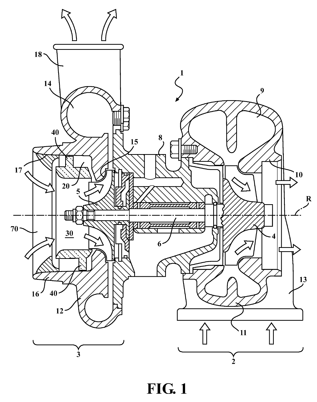
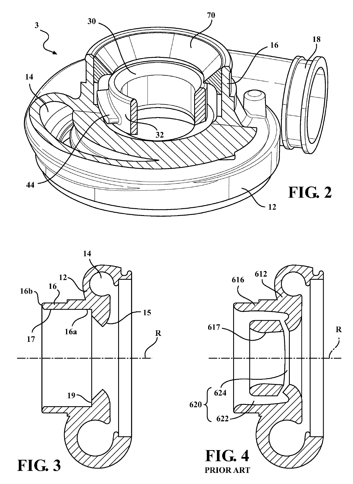
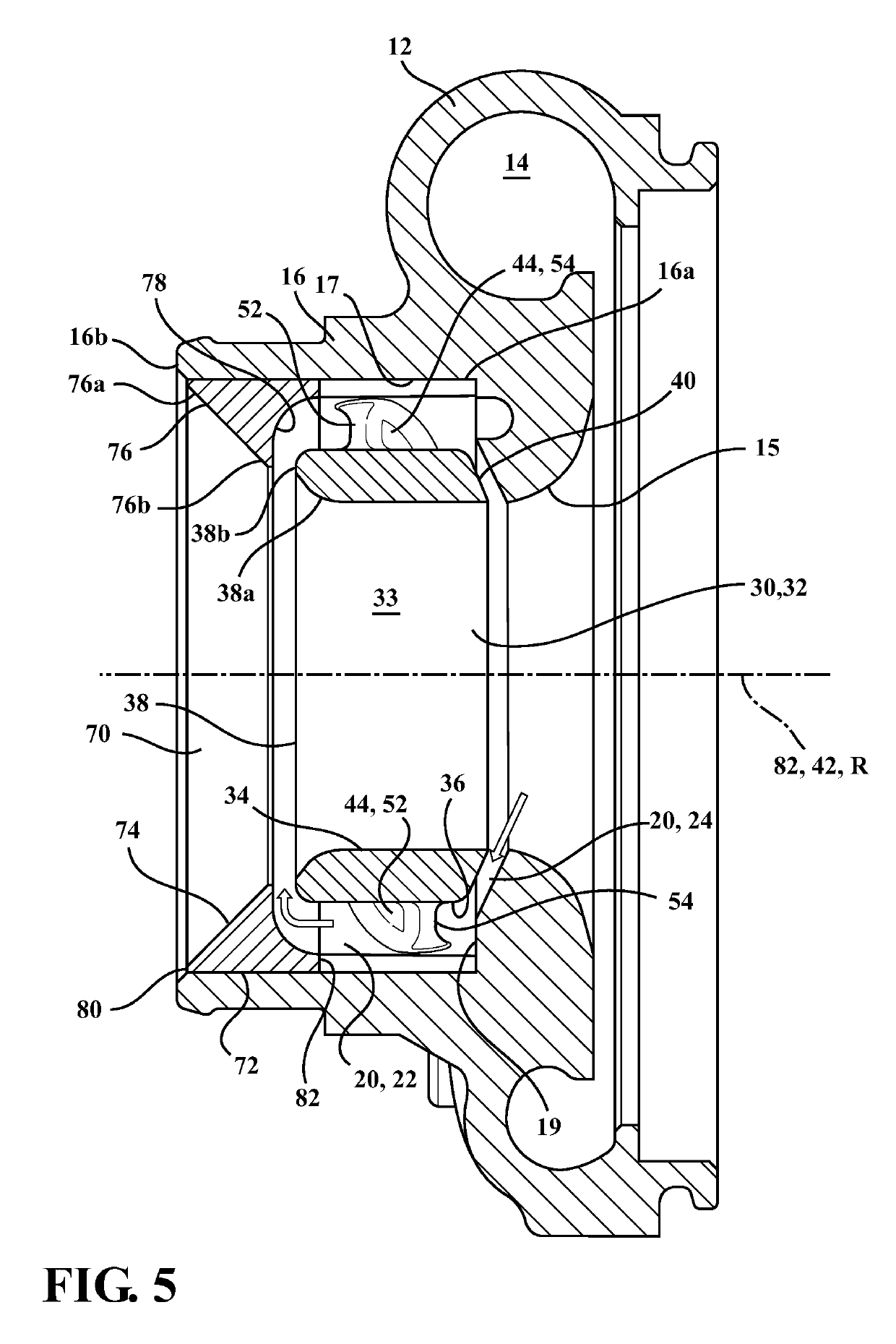
[0039]Referring to FIGS. 1-2, an air inlet 16 of a compressor section 3 of an exhaust gas turbocharger 1 is formed without an integral air recirculation path, and an air recirculation path 20 is instead provided by placing an air flow-enhancing insert 30 within the air inlet 16. In particular, the air flow-enhancing insert 30 is disposed in the compressor air inlet 16, and cooperates with an inner surface 17 of the air inlet to form the air recirculation path 20. The insert 30 is a hollow cylindrical member formed independently (e.g., as a separate entity) from the compressor inlet 16, and is assembled therewith prior to use. The insert 30 has supporting lugs 44 that are shaped and positioned to improve air flow within the air inlet 16 and reduce noise, as discussed further below.

[0040]The exhaust gas turbocharger 1 includes a turbine section 2, the compressor section 3, and a center bearing housing 8 disposed between and connecting the compressor section 3 to the turbine section 2....


PUM


Abstract

An air flow-enhancing insert (30) is configured to be inserted into the air inlet (16) of a compressor (3). The insert includes a hollow, cylindrical inner member (32) and lugs (44) protruding outward from an outer surface (36) of the inner member, each lug having an elongated cross sectional shape and including a leading edge (46), a trailing edge (48), and a long axis (50) that extends between the leading edge and trailing edge, the long axis defining a helix about the outer surface. When the insert (30) is disposed in the compressor air inlet, an air recirculation path (20) is defined between the inner member outer surface, an inner surface (17) of the air inlet, and the lugs. The air recirculation path improves air flow in the compressor, whereby compressor efficiency is improved and noise is reduced.

Description

CROSS-REFERENCE TO RELATED APPLICATION[0001]This application claims priority to and all the benefits of U.S. Provisional Application No. 61 / 912,646, filed on Dec. 6, 2013, and entitled “Reduced Noise Compressor Recirculation,” which is incorporated herein by reference.FIELD OF THE INVENTION[0002]The invention relates to a turbocharger with an improved compressor and more particularly, to a compressor inlet duct including an air flow-enhancing insert.BACKGROUND OF THE INVENTION[0003]Exhaust gas turbochargers are provided on an engine to deliver air to the engine intake at a greater density than would be possible in a normal aspirated configuration. This allows more fuel to be combusted, thus boosting the engine's horsepower without significantly increasing engine weight.[0004]Generally, an exhaust gas turbocharger includes a turbine section and a compressor section, and uses the exhaust flow from the engine exhaust manifold, which enters the turbine section at a turbine inlet, to dri...

Claims


Application Information

Patent Timeline
Patent Type & Authority Patents(United States)
IPC IPC(8): F04D29/68F02M35/12F02B39/00F04D29/28F04D29/42F04D25/04F02B37/12
CPCF04D29/685F02B37/12F02B39/00F04D25/045F04D29/284F04D29/4213F02M35/1288Y02T10/144Y02T10/12
Inventor BURGESS, MARK
Owner BORGWARNER INC
Why Eureka
Try Eureka