
Method and device for transmitting prediction mode of depth image for interlayer video encoding and decoding

a prediction mode and depth image technology, applied in the field of interlayer video encoding and decoding methods, can solve the problems of low quality of synthetic images and almost impossible to achieve stereoscopic images, and achieve the effects of efficient encoded or decoded, reducing device complexity, and efficiently generating images

Active Publication Date: 2019-07-30
SAMSUNG ELECTRONICS CO LTD
View PDF33 Cites 0 Cited by
  • Summary
  • Abstract
  • Description
  • Claims
  • Application Information

AI Technical Summary

Benefits of technology

[0007]In an interlayer video decoding and encoding apparatus and method according to an embodiment, a prediction mode of a depth image may be efficiently encoded or decoded to decrease device complexity and efficiently generate an image when images are synthesized.

Problems solved by technology

Thus, if a network infrastructure, a ground wave bandwidth, etc. are taken into account for the stereoscopic image, the stereoscopic image is almost impossible to achieve although the images are compressed using an encoding apparatus optimized to single-view video coding such as MPEG-2, H.264 / AVC, HEVC, etc.
When the depth image deteriorates, the quality of a synthetic image is low.

Method used


Image

  • Method and device for transmitting prediction mode of depth image for interlayer video encoding and decoding
  • Method and device for transmitting prediction mode of depth image for interlayer video encoding and decoding
  • Method and device for transmitting prediction mode of depth image for interlayer video encoding and decoding

Examples


Embodiment Construction

Advantageous Effects

[0007]In an interlayer video decoding and encoding apparatus and method according to an embodiment, a prediction mode of a depth image may be efficiently encoded or decoded to decrease device complexity and efficiently generate an image when images are synthesized.

[0008]Technical aspects and effects of the present disclosure are not limited to the above description and other aspects will become apparent and more readily appreciated to those of ordinary skill in the art from the following description.

BRIEF DESCRIPTION OF THE DRAWINGS

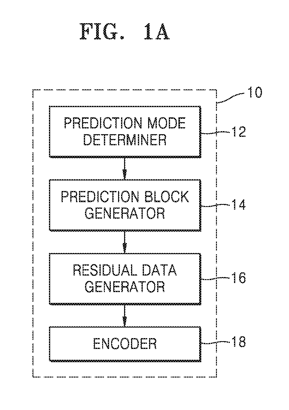
[0009]FIG. 1A is a block diagram of an interlayer video encoding apparatus according to an embodiment.

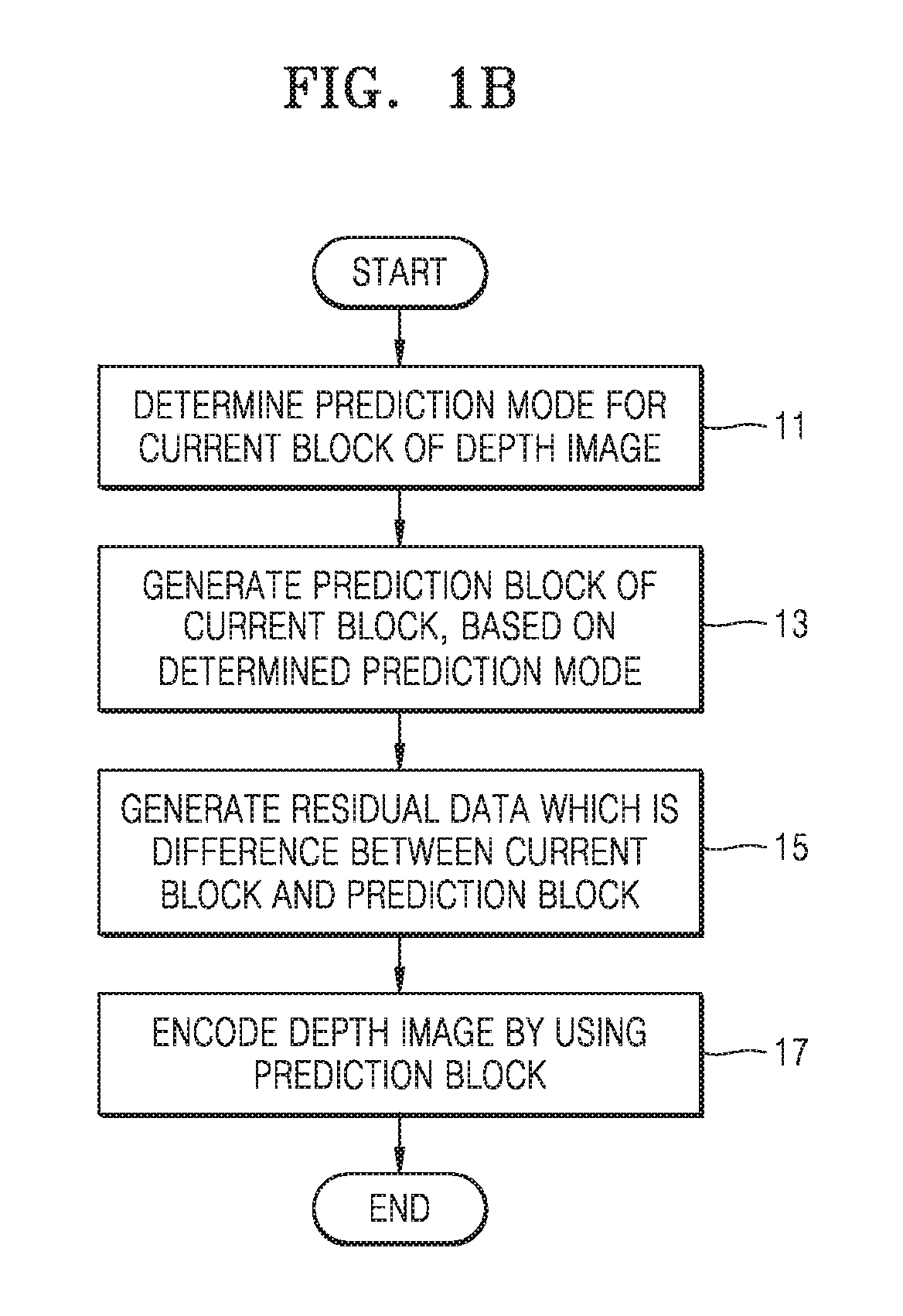
[0010]FIG. 1B is a flowchart of a video encoding method according to an embodiment.

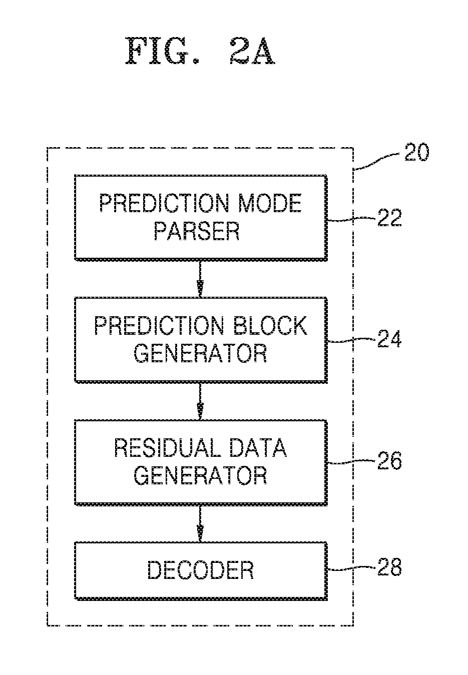
[0011]FIG. 2A is a block diagram of an interlayer video decoding apparatus according to an embodiment.

[0012]FIG. 2B is a flowchart of a video decoding method according to an embodiment.

[0013]FIG. 3 illustrates an interlayer prediction scheme according to...


PUM


Abstract

Provided is an interlayer video decoding method according to an embodiment including obtaining prediction-mode information of a current block of a depth image from a bitstream, generating a prediction block of the current block on the basis of the prediction-mode information, and decoding the depth image by using the prediction block. The obtaining of the prediction-mode information of the current block from the bitstream includes receiving a first flag, a second flag, and a third flag, wherein the first flag indicates whether prediction of the current block by dividing the current block into two or more partitions according to a pattern is permitted, the second flag indicates whether the depth image permits blocks of the depth image to be predicted by dividing the blocks into two or more partitions by using a wedgelet, and the third flag indicates whether the depth image permits the blocks of the depth image to be predicted by dividing the blocks into two or more partitions by using a contour; and receiving a fourth flag from the bitstream when predetermined conditions determined on the basis of the first to third flags are satisfied, wherein the fourth flag represents information regarding a type of a method of dividing the current block into two or more partitions according to the pattern.

Description

[0001]This application is a National stage entry of International Application No. PCT / KR2015 / 006283, filed on Jun. 22, 2015, which claims priority from U.S. Provisional Application No. 62 / 014,811, filed on Jun. 20, 2014 in the United States Patent and Trademark Office. The disclosures of each of the applications are herein incorporated by reference in their entirety.TECHNICAL FIELD[0002]The present disclosure relates to interlayer video encoding and decoding methods, and more particularly, methods of encoding and decoding a prediction mode of a depth image.BACKGROUND ART[0003]A stereoscopic image means a three-dimensional (3D) image which provides information regarding a depth and the shape of a space, as well as information regarding an image. A stereo image provides different viewpoint images to left and right eyes. In contrast, the stereoscopic image provides an image viewed in a different direction whenever an observer changes a viewpoint. Thus, images captured from a plurality ...

Claims


Application Information

Patent Timeline
Patent Type & Authority Patents(United States)
IPC IPC(8): H04N19/597H04N19/176H04N19/70H04N19/187H04N19/503H04N19/107
CPCH04N19/597H04N19/176H04N19/503H04N19/70H04N19/187H04N19/107
Inventor LEE, JIN-YOUNGPARK, MIN-WOOCHO, YONG-JIN
Owner SAMSUNG ELECTRONICS CO LTD
Learn More